Insert and Connect the Power Cord:
15
1) Install the grommet with ¼” center into the rear chassis hole.
2) Gently insert the power cord through this grommet hole until at least 18" (1.5 FT) are through.
Tie a knot at the end of the cord so that 1" of black outside insulation extends past the knot. This
knot will serve as a strain relief. Pull the knot as tight as possible by hand. Gently pull the cord
back through the grommet from outside of the chassis until the knot is snug against the inside face
of the grommet.
3) Connect the power cord’s "Neutral (N)" (also known as "Common" or "Return") wire to the other
lug on the power switch (see Drawing 8). You may find it easier to connect by temporarily rotating
the power switch for access to the solder lugs.
4) Connect the power cord’s "Line (L)" (also known as "Hot") wire to the central lug on the fuse
holder.
5) Connect the power cord’s "Earth (E)" (also known as "Ground") wire to T2(1).
SECTION 7 – Finish Connecting the Transformer and Power Supply Wires
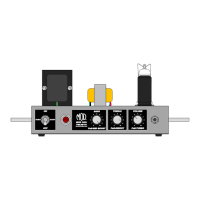
Drawing 8 shows the inside chassis as viewed from the rear and looking at the front, again.
Connect the Power Transformer (TR1) Wires:
1) Connect one of the TR1 red wires to T2(6).
2) Connect the other TR1 red wire to T2(4).
3) Connect the TR1 red/yellow wire to T2(1).
Connect the Output Transformer (TR2) Wires:
1) Connect the TR2 red wire to T2(3).
2) Connect the TR2 blue wire to V2(7).
Connect the Tube Power Supply Wires:
1) Connect white wire (about 5.5") from T2(2) to T4(4).
2) Connect white wire (about 3.5") from T4(4) to T6(5).
3) Connect white wire (about 2") from T6(5) to T5(2).
SECTION 8 – Connect the Tube Filament Wiring
Drawing 9 shows the inside chassis view with the filament wiring connected. Use the green wire for these
connections and try to follow the wiring path in the drawing.