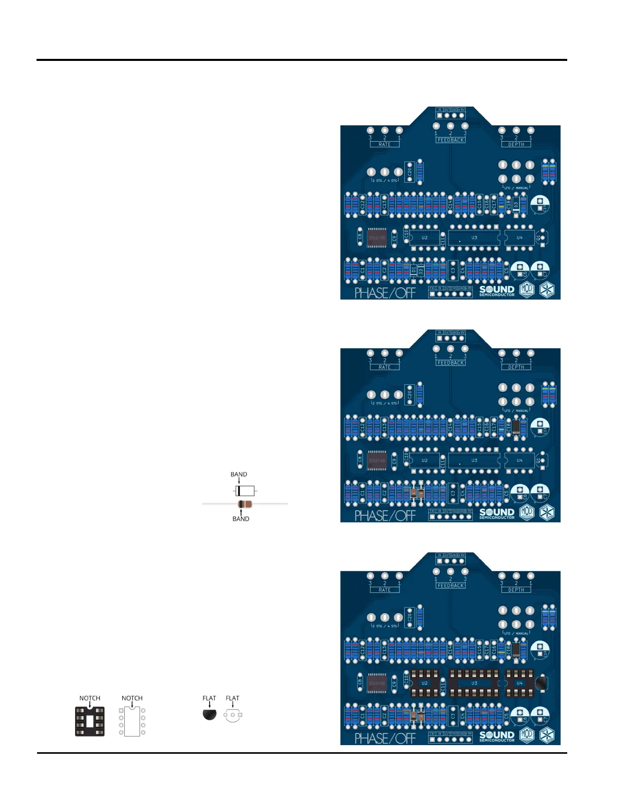
39: Insert an 8-Pin DIP Socket at U2. Be sure to match
the orientation on the silkscreen. Solder this now.
40: Insert a 14-Pin DIP Socket at U3. Be sure to match
the orientation on the silkscreen. Solder this now.
41: Insert an 8-Pin DIP Socket at U4. Be sure to match
the orientation on the silkscreen. Solder this now.
42: Insert the 2N2222A transistor at Q1. Be sure to
match the orientation on the silkscreen. Solder this now.
Part 3: IC Sockets & Transistor
Phase / Off
15
Main PCB Construction
Part 1: Resistors (cont.)
31: Insert a 1MΩ resistor at R31. Its color bands are
brown, black, black, yellow, brown.
32: Insert a 3KΩ resistor at R32. Its color bands are
orange, black, black, brown, brown.
33: Insert a 100Ω resistor at R33. Its color bands are
brown, black, black, red, brown.
34: Insert a 47KΩ resistor at R34. Its color bands are
brown, black, black, red, brown.
35: Insert a 47KΩ resistor at R35. Its color bands are
red, black, black, black, brown. Solder these ve
resistors now.
Locate the three diodes. When inserting each diode,
note the orientation of the band. This should match
the orientation on the silkscreen.
36: Insert a 1N4148 diode at D1.
Part 2: Diodes
37: Insert a 1N4148 diode at D2.
38: Insert the 1N5817 diode at D3. Solder these three
diodes now.
 Loading...