Phase / Off
21
Final Assembly
Part 1: Connect the Footswitch PCB to the Main PCB
Locate the three PCBs and the enclosure. The following steps will cover the nal assembly of the
pedal by connecting and mounting these three boards. Use the BOM and Parts List as references.
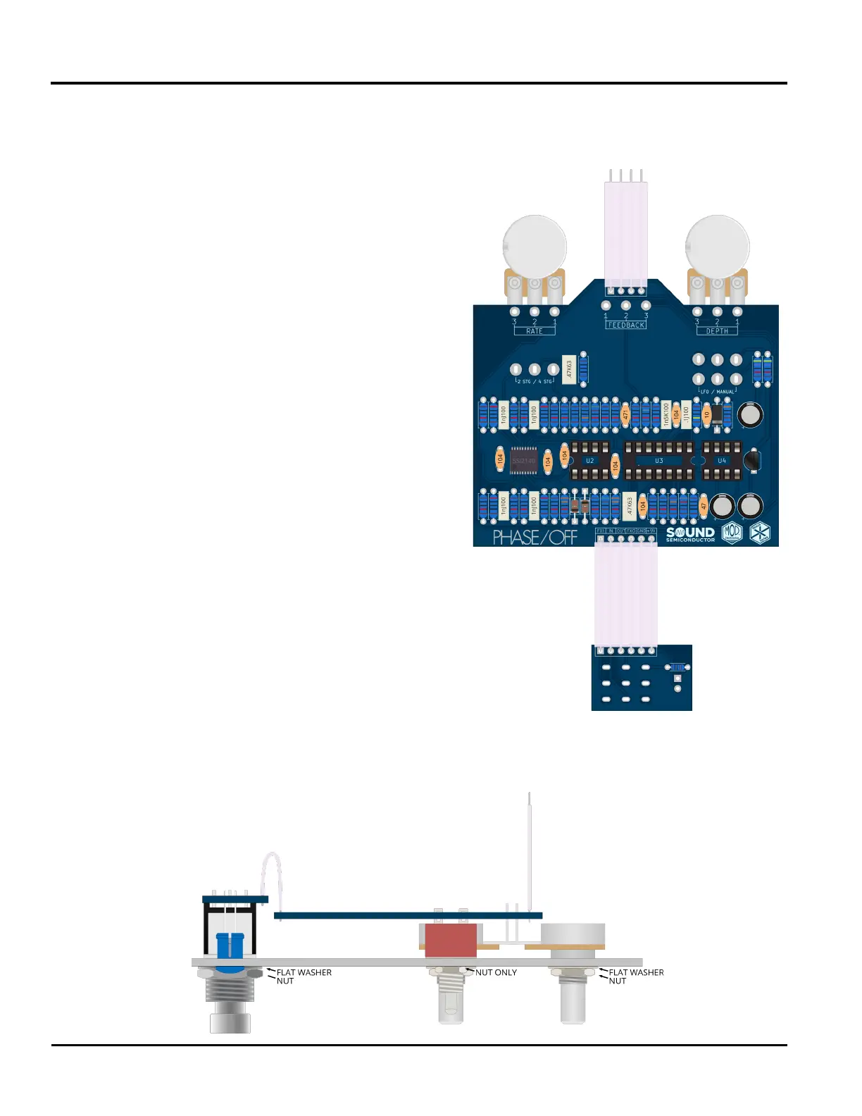
83: Insert the 6 conductor ribbon cable through the
six holes near the logos on side 1 of the main PCB.
Solder all 6 connections now.
84: Insert the 4 conductor ribbon cable through the
four holes near the feedback pot on side 1 of the
main PCB. Solder all 4 connections now.
85: Insert the other side of the 6 conductor ribbon cable
through the six holes on side 1 of the footswitch PCB.
Solder all 6 connections now.
Part 2: Attach the Footswitch PCB & the
Main PCB to the Enclosure
86: Make sure that all mounting hardware has been
removed from the pots and switches. Gently slide both
boards into their mounting holes simultaneously. Be
extra careful with the toggle switches and LED. Make
sure that the LED leads do not bend and that the LED lens
remains ush to the enclosure.
87: Once all parts are fully ush to the interior of the enclosure, begin
attaching the mounting hardware. For the pots and footswitch, use a
metal at washer and then attach the nut. Use a single nut for the
toggle switches. Make sure that the footswitch is not rotating as the nut
is tightened down. Do not overtighten the mounting hardware.
Now is a good time to check over the build to make sure
no steps were missed and that all connections have
been made.
 Loading...