8
6-534.1
Horizontal Vent Only - Category III Determination (Not
Separated Combustion)
• Horizontal vent systems terminate horizontally (sideways)
(an example is shown in Figure 10.1).
• A vent system that terminates vertically but has a
horizontal run that exceeds 75% of the vertical rise is
considered horizontal.
• Horizontal vent configurations are Category III. Additional
requirements are covered in "Section C - 1 Pipe Horizontal
Category III Vent System Installation".
If the vent system to be installed meets ALL these criteria,
proceed to "Section C – Horizontal Vent Only, Category III
Vent System Venting Instructions
Vertical Combustion Air and Vent - Category III Vent
Determination (Separated Combustion)
• Vertical vent systems terminate vertically (up)
(an example is shown in Figure 11.1).
• Determine the venting configuration as follows:
> For two building penetrations through the wall or roof
(one for the combustion air inlet pipe and one for the
vent pipe), proceed to “Section D Vertical Combustion
Air and Vent - Category III Vent Determination
(Separated Combustion) Venting Instructions".
> For a single larger building penetration through the
wall or roof, through which both the combustion air
inlet and vent pipes will pass, proceed to “Section F -
Horizontal or Vertical Combustion Air and Vent
Systems using a Concentric Vent - Category III Vent
System Determination (Separated Combustion)".
Horizontal Combustion Air and Vent - Category III Vent
System Determination (Separated Combustion)
• Horizontal vent systems terminate horizontally
(sideways) (an example is shown in Figure 12.1).
• Determine the venting configuration as follows:
> For 2 building penetrations through the wall or roof
(1 for the combustion air inlet pipe and 1 for the vent
pipe), proceed to “Section E - Horizontal Combustion
Air and Vent - Category III Vent System Determination
(Separated Combustion) Venting Instructions".
> For a single larger building penetration through the
wall or roof, through which both the combustion air
inlet and vent pipes will pass, proceed to “Section F -
Horizontal or Vertical Combustion Air and Vent
Systems using a Concentric Vent - Category III Vent
System Determination (Separated Combustion)".
A22. This unit may be installed with or without the combustion
air intake pipe. Using the vent pipe only allows for greater
maximum vent length but is not considered "separated
combustion" because the combustion air comes from
indoors. Using both a combustion air and vent pipe is
considered "separated combustion" and requires a shorter
maximum vent.
INSTALLATION - VENTING
Vertical Vent Only - Category I Vent Determination
(Not Separated Combustion)
• Vertical vent systems terminate vertically (up) (an example
is shown in Figure 9.1).
• The horizontal portion of the vent run cannot exceed 75%
of the vertical rise (Example: If the vent height is 10', the
horizontal portion of the vent system cannot exceed 7.5').
• The vent terminates a minimum of 5' above the vent
connector on the unit.
• If the vent system to be installed meets ALL these criteria,
proceed to "Section B – Vertical Vent Only, Category I Vent
System Venting Instructions".
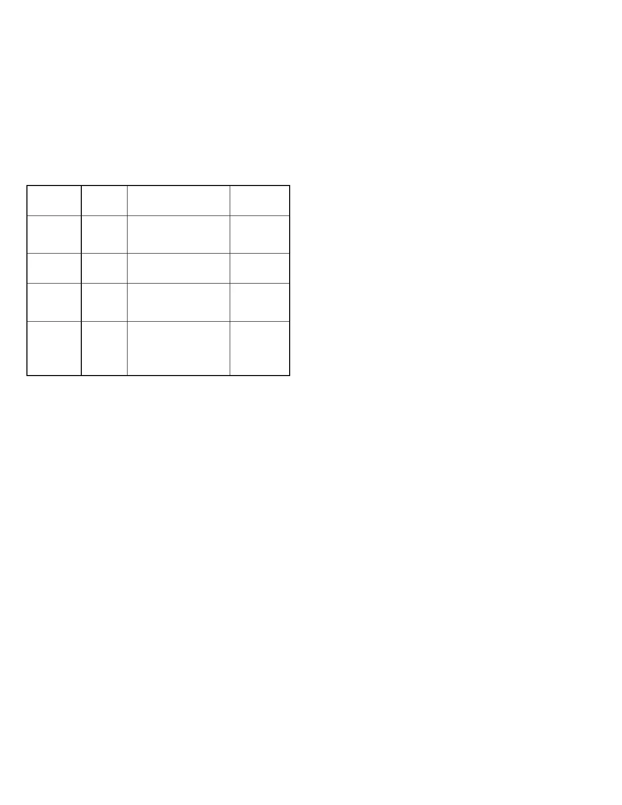
# of pipes
(horizontal/
vertical) Category Description
Venting
Requirements
Vertical Vent
Pipe Only
I
Negative vent pressure
Non-condensing
Follow
standard
venting
requirements.
Not applicable
to this product
II
Negative vent pressure
Condensing
Condensate
must be
drained.
Horizontal
Vent Only All
two pipe
systems
III
Positive vent pressure
Non-condensing
Vent must be
gas tight.
Not applicable
to this product
IV
Positive vent pressure
Condensing
Vent must be
liquid and
gas tight.
Condensate
must be
drained.
Note: Vent connectors serving Category I appliances shall not be connected into
any portion of mechanical draft systems operating under positive pressure.
Table 8.1 - ANSI Unit Heater Venting Requirements
A23. In addition to following these general instructions, specific
instructions for vertical and horizontal vent systems in 1
pipe, 2 pipe or 2 pipe concentric vent configurations must
also be followed. Table 8.1 outlines the differences: