4
Operating Instruction
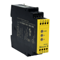
ESR4-NO-30
Basic device for Emergency-Stop and Safety Gate Applications
• Base device to IEC 60204-1 and EN 954 -1 for single-channel and two-channel emergency
stop monitoring.
• Category 4 to EN954-1
• Stop category 0 to EN 60204-1
• Manual or automatic start
• With/without cross monitoring
• Feedback circuit for monitoring external contactors
• 3 enabling current paths, NO contacts, positively driven
• For processing signals from the output signal switching devices (OSSD) of a light grille acc. to
DIN EN 61496-1
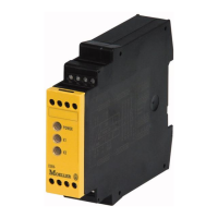
Front View
POWER
K1
K2
LED green Power Supply
LED green Relay K1
LED green Relay K2
Safety Instructions
Only trained professional electricians may in-
stall, startup, modify, and retrofit this equipment!
Disconnect the device / system from all power
sources prior to starting any work! If installation
or system errors occur, line voltage may be pre-
sent at the control circuit in devices without DC
isolation!
Observe all electrical safety regulations issued
by the appropriate technical authorities or the
trade association. The safety function can be
lost if the device is not used for the intended
purpose. Opening the housing or any other ma-
nipulation will void the warranty.
Caution!
If the device has been subjected to improper or
incorrect use it must no longer be used, and the
guarantee loses its validity. Impermissible condi-
tions include:
strong mechanical stress, for example through a
fall, or voltages, currents, temperatures or hu-
midity outside of the specifications.
Before starting up your machine/plant for the
first time, please be sure to check all the safety
functions according to valid regulations, and
observe the specified test cycles for safety
equipment.
Caution!
Perform the following precautionary steps prior
to installation, assembly, or disassembly:
1. Disconnect supply voltage to the equipment
/ system prior to starting any work!
2. Lockout/tag the equipment / system to pre-
vent accidental activation!
3. Confirm that no voltage is present!
4. Ground the phases and short to ground!
5. Protect against adjacent live components
using guards and barriers!
6. The devices must be installed in a cabinet
with a protection class of at least IP 54.
Caution!
Limited contact protection!
Protection type according to EN 60529
Housing/terminals: IP 40/ IP 20.
Finger-proof acc. to VDE 0660 Part 514.
Description of Device and Function
This device is a two-channel safety switching device for emergency stop applications with self-
monitoring on each ON-OFF cycle. It conforms to EN 60204-1 and is equipped with positively
driven relays.
Basic function: After supply voltage has been connected to terminals A1/A2 and the safety inputs
closed, operating the reset button closes the enabling current paths (manual start). When the safety
inputs are opened/de-excited the enabling current paths will open.
Operating modes / system functions
• One- or two-channel activation With single-channel activation both safety channels CH1 and
CH2 are connected in parallel, with two-channel activation they are connected separately.
• Without cross monitoring Both safety channely are connected to positive potential (S12 and
S31 to S11).
• With cross monitoring Safety channel CH1 is connected to positive potential (S11 to S12)
and safety channel CH2 to negative potential (S21 to S22).
• Manual start When the safety inputs are closed, a button is used to open reset input S34
(triggering with falling edge) or to close reset input S35 (triggering with rising edge).
• Automatic start Reset input S35 is connected to S33. The device starts with the rising edge
of the signal on safety input S12.
• Starting lockout After supply voltage has been connected and the safety inputs closed, the
enabling paths will not close. Starting is only possible after the reset button has been oper-
ated. For starting lockout the reset inputs have to be activated with the button, as in manual
start mode.
• Restarting lockout No restart after the safety inputs have been opened and closed. Restart-
ing is only possible after the reset button has been operated. For restarting lockout the reset
inputs have to be activated with the button, as in manual start mode.
• OSSD-compatible OSSD signals from a light barrier or other safety sensors with semiconduc-
tor outputs can be processed. Test pulses < t
TP
do not influence the device functions. Test
pulses > t
TP
can lock the device.
• Synchro-check With two-channel activation both safety channels are monitored together with
synchronous time t
S
. Safety channel CH1 must close before CH2 and bridge S33/S35 must be
connected. If CH2 closes before CH1, the synchronous time t
S
= ∞.
Please observe instructions from safety authorities.
9
Caractéristiques techniques
Circuit d’alimentation
Tension nominale U
N
AC/DC 24 V
AC 115 - 120 V, AC 230 V
Puissance assignée DC DC 2,0 W
Puissance assignée AC AC 2,4 W / 4,4 VA
Ondulation résiduelle U
SS
2,4 V
Fréquence nominale 50 ... 60 Hz
Plage de la tension de service 0,85 ... 1,1 x U
N
Fusible pour alimentation circuit de commande résistant aux courts-circuits
Circuit de commande
Sorties (S11, S21)
Tension de sortie nominale (S11 contre S21) DC 22 V
Tension à vide (uniquement appareils AC) < 40 V
Courant de sortie 100 mA
Résistant aux courts-circuits oui
Entrées (S12/S33, S31/S22, S34, S35)
Plage de la tension d’entrée (uniquement pour les appareils DC) DC 17,4 V à DC 26,4 V
Courant nominal / courant de pointe
(entrées de sécurité S12/S33, S31/S22)
40 mA / 100 mA
Courant nominal / courant de pointe (entrées de reset S34, S35) 5 mA / 50 mA
Temps
Temps d’impulsion de test admis t
TP
/ fréquence de test ≤ 1000 µs / ≤ 10 s
-1
Temps de réponse t
A1
(entrée de reset S34) 20 ms à 40 ms
Temps de réponse t
A2
(entrée de reset S35) 200 ms à 600 ms
Durée mini de maintien t
M
(entrées de reset S34, S35) > 80 ms
Temps de réarmement t
W
≥ 100 ms
Temps de relâchement t
R
(K1, K2)
< 25 ms
Temps de synchronisation t
S
≈ 200 ms
Circuit de sortie
Contacts de sortie
Equipement des contacts 3 contacts de travail, à guidage forcé
Tension nominale de coupure U
n
AC 230 V / DC 300 V
Courant continu max. I
n
pour chaque contact 6 A
AC/DC 24 V 12 A Courant total max. de tous les contacts
AC 115 - 120 V, AC 230 V 8 A
AC-15 : Ue 230 V, Ie 4 A (360 h
-1
) DC-13 : Ue 24 V, Ie 4 A (360 h
-1
)
Catégorie d’utilisation selon IEC 947-5-1
AC-15 : Ue 230 V, Ie 3 A (3600 h
-1
) DC-13 : Ue 24 V, Ie 2,5 A (3600 h
-1
)
Durée de vie mécanique (commutations) 10
6
Caractéristiques générales
Entrefers et lignes de fuite entre les circuits électriques selon DIN VDE 0110-1:11.2003
Surtension transitoire assignée 4 kV
Degré de pollution de l’appareil: à l’intérieur / à l’extérieur 2 / 3
Tension assignée AC 300 V
Classe de protection selon EN 60529 Boîtier / bornes IP 40 / IP 20
Température ambiante / de stockage -25 ... +55 / -25 ... +75 °C
Poids appareils DC 0,21 kg
appareils AC 0,25 kg
Données sur les bornes et les connexions
Unifilaire (fil rigide) ou fils de faible diamètre (multibrins) 1 x 0,14 mm² à 2,5 mm² 2 x 0,14 mm² à 0,75 mm²
Longueur de dénudation max. 8 mm
Fil à faible diamètre (multibrins) avec embout selon DIN 46228 1 x 0,25 mm² à 2,5 mm² 2 x 0,25 mm² à 0,5 mm²
Couple de serrage max. 0,5 à 0,6 Nm
Sections de connexion AWG 18-16 utiliser uniquement conducteurs en Cu Pour homologations UL (Underwriters
Listing Loboratories) et CSA (Canadian
Standards Associations)
Couple de serrage max. 0,79 in-lbs
 Loading...