Do you have a question about the Moen 5900 Series and is the answer not in the manual?
Warning about turning off water, relieving pressure, and checking cartridge retainer nuts to prevent injury or damage.
Instructions for applying putty, placing the spout, and hand-tightening the mounting nut.
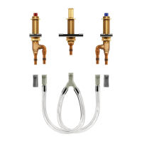
Guide for positioning valve bodies under the sink and tightening top mounting nuts.
Attaching escutcheons, bottom mounting nuts, and connecting supply tubing to the spout union tee.
Testing the lift rod operation and adjusting the spout if necessary.
Installing handle hubs, adapters, and handles, including specific instructions for hot and cold side orientation.
Connecting water supplies to valve bodies using tailpiece nuts and ensuring a wrench-tight joint.
Procedure to correct reversed handle rotation by adjusting the cartridge and handle adapter.
Open both hot and cold cartridges before turning on water supply.
Turn on water supplies and let water run for 15 seconds to flush debris.
Turn off cartridges, unscrew aerator, and clean debris from the screen.
Replace aerator and check the entire system for leaks.
Remove plug button, handle screw, and handle hub from the faucet.
Loosen cartridge nut and remove it with the stem guide and upper handle adapter.
Reassemble handle hub and screw after removing cartridge assembly.
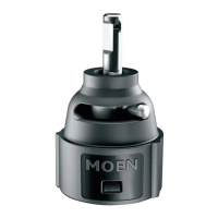
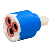
Pull the handle hub to remove the cartridge straight up from the valve body.
Attach handle adapter and hub to the new cartridge using the handle screw.
Insert cartridge into valve body, pressing firmly and rotating to align key with notch.
Observe handle rotation and orientation for potential adjustments.
Install cartridge nut with stem guide over the handle adapter and tighten securely.
Reinstall handle parts following the provided illustration.
Clean drain opening and apply plumber's putty around the drain seat.
Apply pipe joint compound, insert drain body, and screw on the drain seat.
Tighten mounting nut, clean excess putty, and connect tailpipe to drain body.
Instructions for positioning the drain plug using Vandalproof or Easy Removal methods.
Install lift rod with knob and secure the lift rod strap to the pivot rod.
Adjust lift rod and knob for clearance and tighten the lift rod strap screw.
Steps to reduce potential lead exposure from brass faucets, including running water and using cold water.
Contact numbers for product, installation, replacement parts, and warranty inquiries.
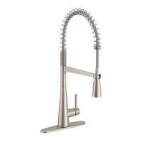
| Product Type | Kitchen Faucet |
|---|---|
| Number of Handles | 1 |
| Supply lines included | Yes |
| Valve Type | Ceramic Disc |
| ADA Compliant | Yes |
| Warranty | Limited Lifetime |
| Series | 5900 |
| Finish | Chrome |