28
5
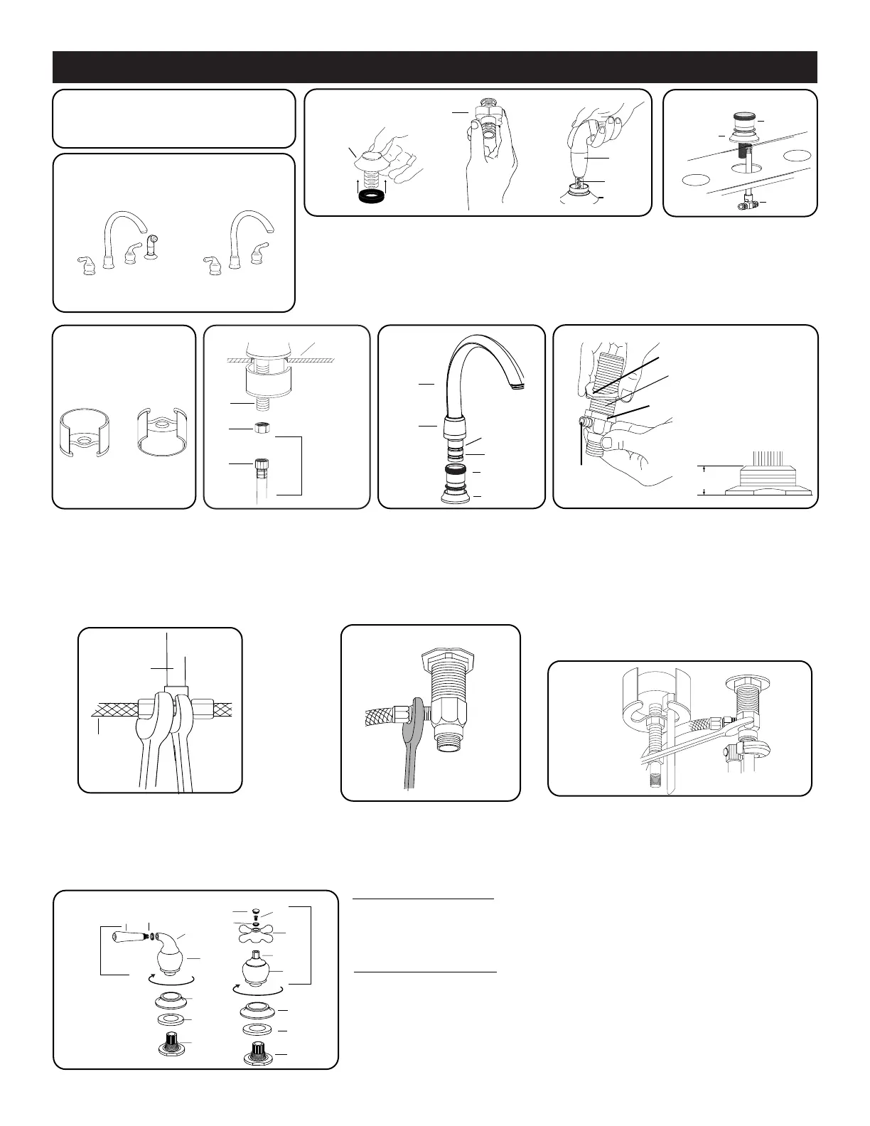
4. Install spout deck ring (27)
onto spout valve body
(25). Attach T-Connector
(31) and orient tee ends
to face valves as pictured
above.
27
25
31
4
3. Locate foam gasket on hose guide (36) by sliding gasket onto
shank and tucking outer edge of gasket under the hose guide
(36). Do not drive the center area of the gasket up into the hose
guide. Install hose guide (36) through hole in sink. From under
sink, thread extended locknut (37) (either side up) on shank of
hose guide and tighten by hand. Feed spray head (35) and hose
(34) down through the hose guide (36) (do not connect spray
hose to faucet until step 5 below).
3
37
35
34
36
36
Various faucet models have slight
differences in installation procedures.
Please review all instructions before
installation. Go to Step 2.
1
2
BE SURE MOUNTING AREA IS CLEAN AND DRY
For Side Spray model only,
go to Step 3
For without Spray model,
go to Step 4
HINT: When using flexible supplies (not included), we
recommend supply lines be installed onto threaded fittings
before placing valves through sink holes. See Step 7
26
29
33
11.ALL MODELS: Insert gasket (14) into bottom of
escutcheon (13). Center escutcheon over valve
bodies. Rotate stem extensions (12) to off position:
clockwise for hot, counterclockwise for cold.
Position lever handle assembly (5) 90° away
from spout. For cross handle assembly (11),
position in desired orientation. Holding lever (1)
or cross (10) handle, hand tighten handle hub (4)
clockwise. Make connections to supply lines.
Faucet flushing is required, see faucet flushing
instructions on page 3.
11
9. With a wrench, fasten ends of supply
hoses (32) to valve bodies (39) (you
may have to loop supply lines).
10
10. Using a basin wrench make final tightening
of all mounting nuts (hold valve bodies from
turning using another wrench on flats of
valve bodies). Check spout alignment.
LEVER HANDLE MODELS
Install lever handle (1) with color
ring (2) into handle hub/elbow
assembly (3,4) and hand tighten
CROSS HANDLE MODELS
Place cross handle insert (10)
onto handle skirt (9), insert han-
dle screw (7) through color ring
(8) and cross handle insert and
tighten. Install plug button (6)
over screw head.
1
3
5
7
11
9
10
14
12
13
2
4
14
12
13
4
8
8. From below sink, attach supply hoses
(32) by holding T-Connector (31) with
wrench. Use an adjustable wrench to
fasten supply hose nut to T-Connector.
CAUTION: DO NOT TWIST THE
TEE CONNECTOR.
25
VALVE MOUNTING NUT
MOUNTING WASHER
39
TOP MOUNTING
NUT
SPRAY
MODELS
8
31
32
5. From under sink, install mounting bracket (28) over
threaded shank (26) on spout body and install mounting
nut (29) onto threaded shank. BE SURE TEE IS STILL
ALIGNED AS SHOWN IS STEP 4. Make final tightening
of mounting nut with the mounting tool (38) provided.
FOR SPRAY MODEL ONLY - Connect spray hose swivel
nut (33) onto the threaded shank on spout body (26).
7. Screw valve mounting nuts down the valve
bodies and drop on the mounting washers.
NOTE: CHECK STEM EXTENSIONS INSIDE
VALVE BODY FOR HOT (RED) SIDE VALVE
AND COLD (BLUE) SIDE VALVE. From under
sink, slide valve bodies up through holes. Screw
top mounting nuts down until tops of valve bodies
are 5/8" (16mm) to 11/16" (18mm) from top of
sink/deck. Position valves making sure outlets
on valves are facing in toward the T-Connector.
Hand tighten the mounting nuts under the sink.
9
32
39
6
6. Carefully raise spout nut
(23). Apply silicone grease
(42) to O-ring (21) and
retaining ring (20). Install
spout (18) into spout body
(25). Thread spout nut hand
tight to secure spout.
21
20
 Loading...