HEATER
INSTALLATION
Step
1:
Fill
Out
Owner Registration
Card
Remove
your owner registration card from
the
plastic
envelope
containing
the
owner's
guide.
It
should
be
filled
out and
mailed
as
soon
as
possible.
Step
2:
Check
for
Parts
Before
discarding packing materials,
be
sure
you
have
located
the
following:
Manual
Gas
Valve
Conversion
Kit
Flue
Pipe
Sleeve
Nut
Tray
Room Temp. Sensor (attached
to the
rear
of the
heater)
Cardboard Template
"STANDARD" Damper
"EXTENSION" Damper
Wall Clamps
(2)
Rubber Packing
Joint
Pipe
Cloth
Insulation
Cover
Outer Flange
Pipe
Holder
Small
Bag of
Screws
Tapping, Type
A -
#8x
3
A
Tapping, Type
A -
#8x
5
/ie
(}££Q£XX>
For
securing
sleeve
and
wall
clamps
(Jxxs>
For
securing
wall
clamps
SIZE
#8 X 3/4
Tapping
#8
X
Vie
Tapping
Fig.
3
Step
3:
Choose
a
Location
for
Your
Heater
In
choosing
a
location
for
your
heater,
the
following
guidelines
must
be
considered:
•The heater
may be
installed
on
combustible
flooring
on
the
metal
tray
provided.
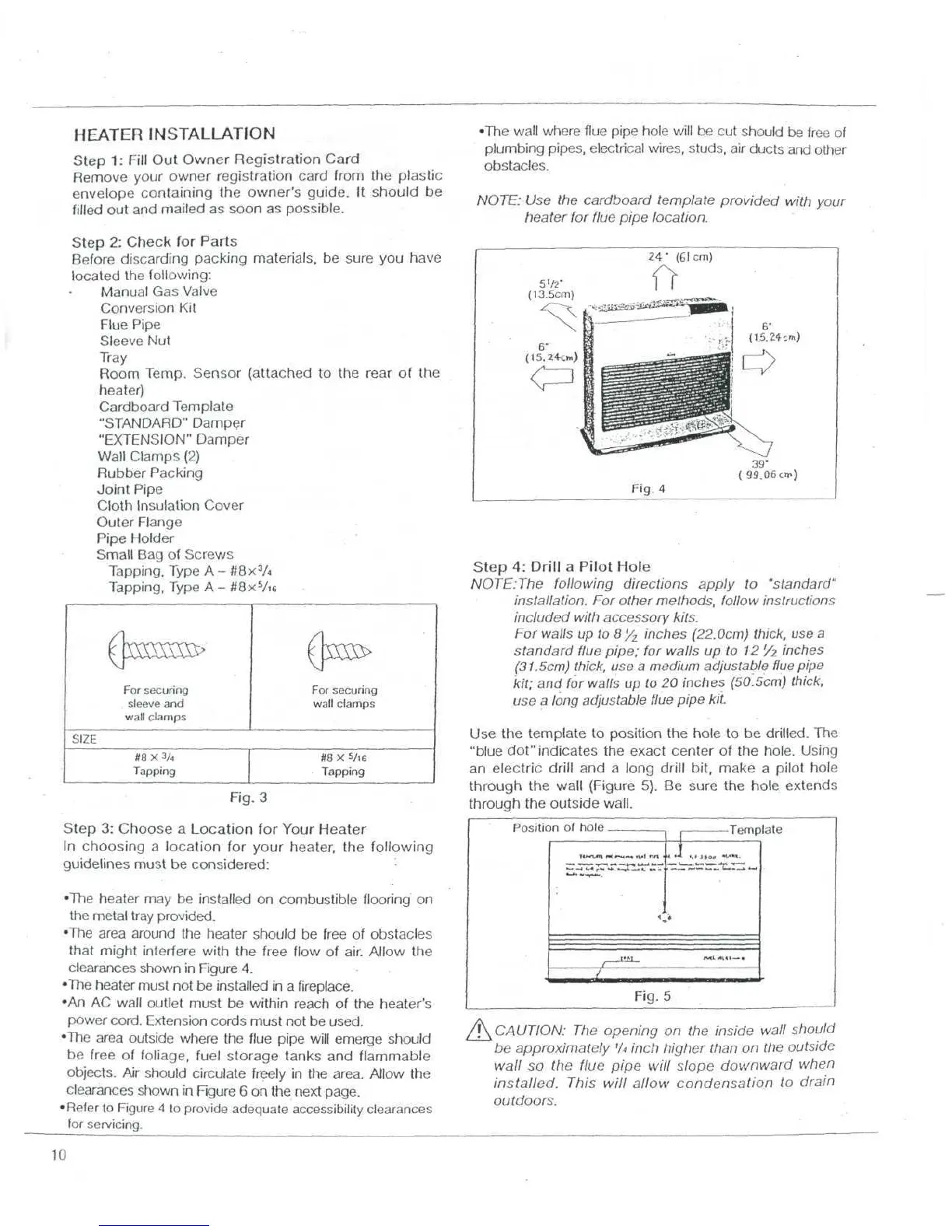
•The area around
the
heater
should
be
free
of
obstacles
that might interfere with
the
free flow
of
air. Allow
the
clearances shown
in
Figure
4.
•The heater must
not be
installed
in a
fireplace.
•An AC
wall outlet must
be
within
reach
of the
heater's
power
cord.
Extension cords must
not be
used.
•The area outside where
the
flue
pipe
will
emerge
should
be
free
of
foliage, fuel storage tanks
and
flammable
objects.
Air
should
circulate
freely
in the
area. Allow
the
clearances shown
in
Rgure
6 on the
next page.
•Refer
to
Figure
4 to
provide
adequate
accessibility
clearances
for
servicing.
•The
wall where
flue
pipe hole
will
be cut
should
be
free
of
plumbing
pipes, electrical
wires,
studs,
air
ducts
and
other
obstacles.
NOTE:
Use the
cardboard template provided with your
heater
for
flue
pipe location.
Fig.
A
(
99.06
cm)
Step
4:
Drill
a
Pilot Hole
NOTE:The
following directions apply
to
"standard"
installation.
For
other
methods,
follow
instructions
included
with
accessory kits.
For
walls
up to
8'/
z
inches (22.0cm)
thick,
use a
standard
flue
pipe;
for
walls
up to
12
'/z
inches
(31.5cm)
thick,
use a
medium
adjustable
flue
pipe
kit;
and
for
walls
up to 20
inches (50.5cm)
thick,
use a
long
adjustable
flue
pipe kit.
Use
the
template
to
position
the
hole
to be
drilled.
The
"blue dot" indicates
the
exact center
of the
hole. Using
an
electric
drill
and a
long
drill
bit, make
a
pilot hole
through
the
wall
(Figure
5). Be
sure
the
hole
extends
through
the
outside wall.
Positic
n
nf
h<">lp
<,
—
Template
r=teaSi-t=S-
^x^
/
Fig.
5
^CAUTION:
The
opening
on the
inside
wall
should
be
approximately
'A
inch higher
than
on the
outside
wall
so the
flue
pipe
will slope downward when
installed.
This
will
allow
condensation
to
drain
outdoors.
10