4.
If it is necessary to reset the float level, bend the
float near the shaft to obtain the correct level.
Throttle Stop
Screw
The throttle stop screw is located on the throttle shaft
lever (side of carburetor by ignition coil). It must be
adjusted and set for
1/32-inch
clearance (0.79 mm)
over the manifold surface when the generating set is
running with no
load.
See Figure 31.
SET THIS DISTANCE AT 1/32 (0.79 mm)
WHEN GENERATING SET IS RUNNING
AT NO LOAD.
SENSITIVITY
CLIP
SPRING TENSION
ADJUSTMENT
SPEED
GOVERNOR /^ BOOSTER
SPRING ir^\ INTERNAL
SPRING
BRACKET
SPEED
BOOSTER
SPEED BOOSTER
EXTERNAL SPRING
BOOSTER EXTERNAL
SLIDE ADJUSTMENT
FIGURE 31. THROTTLE STOP SCREW SETTING
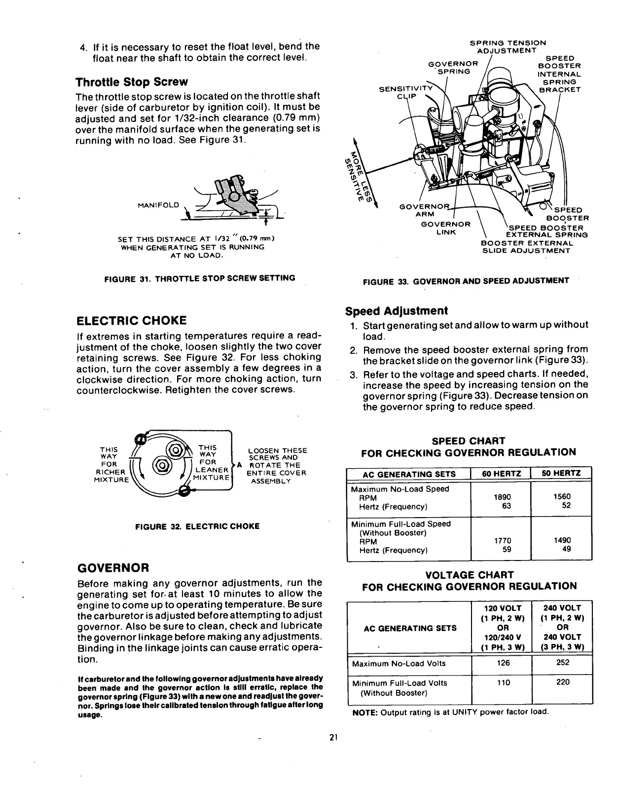
FIGURE 33. GOVERNOR AND SPEED ADJUSTMENT
ELECTRIC
CHOKE
If extremes in starting temperatures require a read-
justment of the choke, loosen slightly the two cover
retaining screws. See Figure 32. For less choking
action,
turn the cover assembly a few degrees in a
clockwise direction. For more choking action, turn
counterclockwise. Retighten the cover screws.
Speed
Adjustment
1.
Start generating set and allow to warm up without
load.
2.
Remove the speed booster external spring from
the bracket slide on the governor link (Figure 33).
3. Refer to the voltage and speed charts. If needed,
increase the speed by increasing tension on the
governor spring (Figure
33).
Decrease tension on
the governor spring to reduce speed.
LOOSEN THESE
SCREWS AND
•A ROTATE THE
ENTIRE COVER
ASSEMBLY
FIGURE 32. ELECTRIC CHOKE
GOVERNOR
Before making any governor adjustments, run the
generating set for-at least 10 minutes to allow the
engine to come up to operating temperature. Be sure
the carburetor is adjusted before attempting to adjust
governor. Also be sure to clean, check and lubricate
the governor linkage before making any adjustments.
Binding in the linkage joints can cause erratic opera-
tion.
If carburetor and the following governor adjustments have already
been made and the governor action Is still erratic, replace the
governor spring (Figure 33) with a new one and readjust the gover-
nor. Springs lose their calibrated tension through fatigue after long
usage.
SPEED
CHART
FOR
CHECKING
GOVERNOR
REGULATION
AC GENERATING SETS
60 HERTZ
50 HERTZ
Maximum No-Load Speed
RPM
Hertz (Frequency)
1890
63
1560
52
Minimum Full-Load Speed
(Without Booster)
RPM
Hertz (Frequency)
1770
59
1490
49
VOLTAGE
CHART
FOR
CHECKING
GOVERNOR
REGULATION
AC GENERATING SETS
120 VOLT
(1 PH, 2 W)
OR
120/240 V
(1 PH, 3 W)
240 VOLT
(1 PH, 2 W)
OR
240 VOLT
(3 PH, 3 W)
Maximum No-Load Volts
126
252
Minimum Full-Load Volts
(Without Booster)
110
220
NOTE:
Output rating is at UNITY power factor
load.
21