Ml O
M2 O
M3
6
M4 Q
TRANSFER
SWITCH
Ml O-
120V
M2
M3 O
120V
M4 O
r
y
0
^ !
-TRANSFER
SWITCH
120V
120V
1
-LINE
120V
ONLY WHEN
CONNECTED
TO GEN.
L
O
A
D
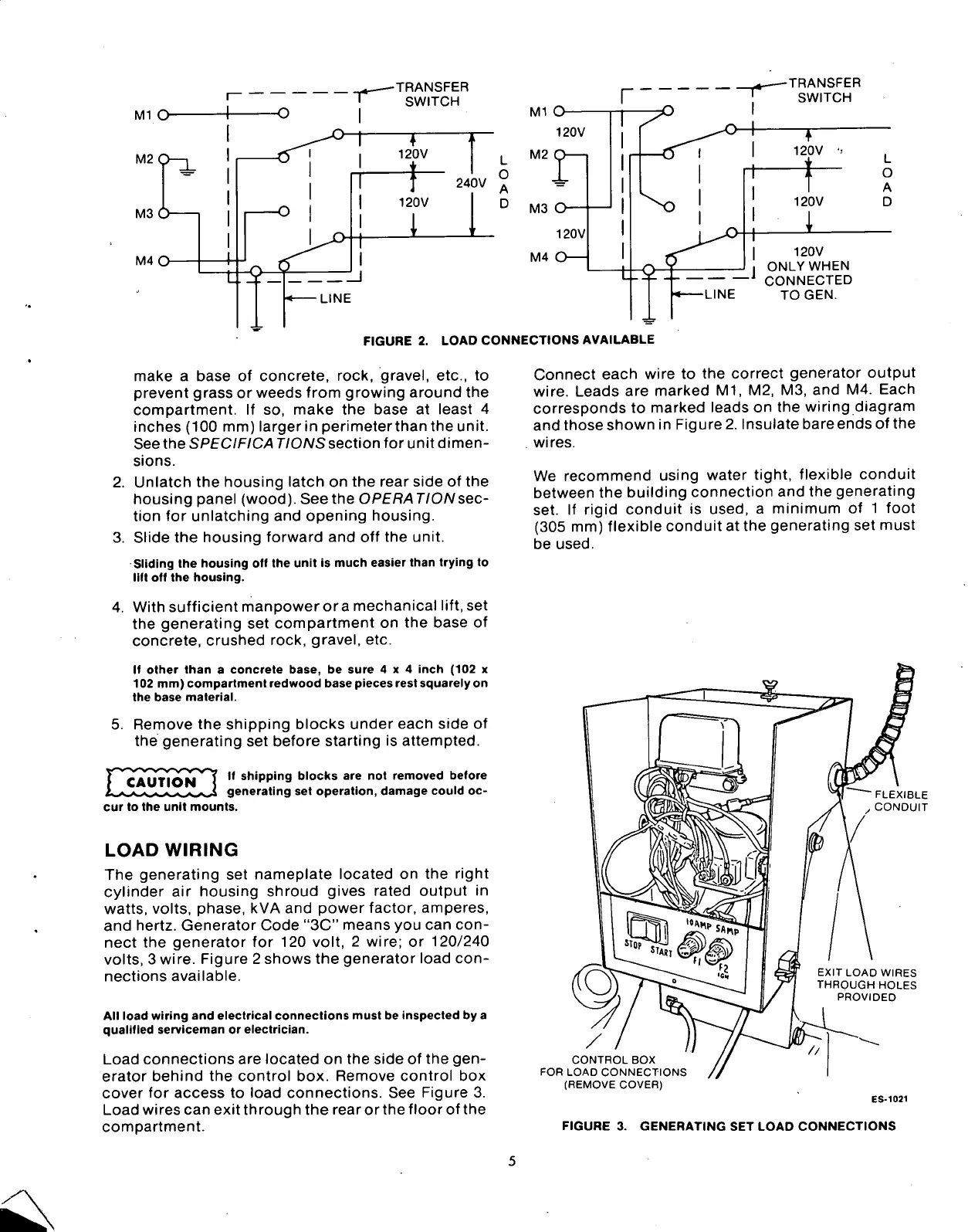
FIGURE 2. LOAD CONNECTIONS AVAILABLE
make a base of concrete, rock, gravel, etc., to
prevent grass or weeds from growing around the
compartment. If so, make the base at least 4
inches (100 mm) larger in perimeter than the unit.
See the SPECIFICA TIONS section for unit dimen-
sions.
2.
Unlatch the housing latch on the rear side of the
housing panel (wood). Seethe OPERATION sec-
tion for unlatching and opening housing.
3. Slide the housing forward and off the unit.
Sliding the housing off the unit is much easier than trying to
lift off the housing.
4.
With sufficient manpowerora mechanical lift, set
the generating set compartment on the base of
concrete, crushed rock, gravel, etc.
If other than a concrete base, be sure 4x4 inch (102 x
102 mm) compartment redwood base pieces rest squarely on
the base material.
5. Remove the shipping blocks under eacn side of
the generating set before starting is attempted.
CAUTION
If shipping blocks are not removed before
generating set operation, damage could oc-
cur to the unit mounts.
LOAD
WIRING
The generating set nameplate located on the right
cylinder air housing shroud gives rated output in
watts,
volts, phase, kVA and power factor, amperes,
and hertz. Generator Code "3C" means you can
con-
nect the generator for 120 volt, 2 wire; or 120/240
volts,
3 wire. Figure 2 shows the generator load
con-
nections available.
All load wiring and electrical connections must be inspected by a
qualified serviceman or electrician.
Load connections are located on the side of the
gen-
erator behind the control box. Remove control box
cover for access to load connections. See Figure 3.
Load wires can exit through the rear or the floor of the
compartment.
Connect each wire to the correct generator output
wire.
Leads are marked Ml, M2, M3, and M4. Each
corresponds to marked leads on the wiring diagram
and those shown in Figure
2.
Insulate bare ends of the
wires.
We recommend using water tight, flexible conduit
between the building connection and the generating
set. If rigid conduit is used, a minimum of 1 foot
(305 mm) flexible conduit at the generating set must
be used.
~ FLEXIBLE
/
CONDUIT
EXIT LOAD WIRES
THROUGH HOLES
PROVIDED
CONTROL BOX
FOR LOAD CONNECTIONS
(REMOVE COVER)
ES-1021
FIGURE 3. GENERATING SET LOAD CONNECTIONS