33
G.
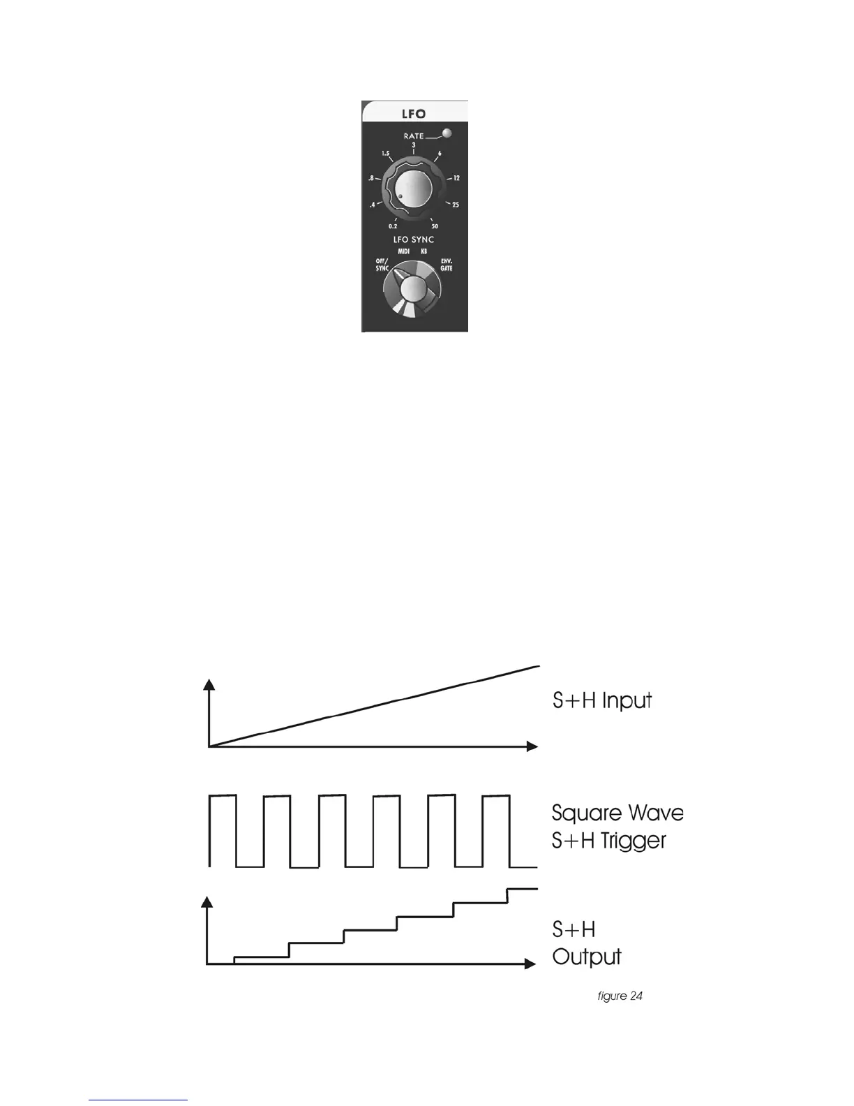
LFO/ SAMPLE AND HOLD
The Voyager has a dedicated LFO and SAMPLE and HOLD. The LFO produces
triangle and square waves that oscillate from .2 to 50 Hz. There are triangle and
square wave outputs that can be selected as Modulation sources in the Mod
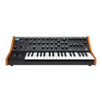
Busses. The Square wave is routed to the Sample and Hold trigger input, and the
noise source is routed to the sample and hold input. For each cycle of the LFO, the
voltage at the input of the sample and hold circuit is held until the next trigger
event. Noise is a random signal, so the voltage that appears at the output of the
sample and hold is a random voltage that changes in time with the LFO. If a plug is
inserted into the sample and hold gate input on the back Panel, it will disconnect
the LFO from triggering the sample and hold circuit. A gate signal or footswitch will
trigger the sample and hold circuit. Similarly, a plug inserted into the Sample and
Hold input Jack disconnects the noise from the S+H input. In this circumstance
when the S+H circuit is triggered, the voltage at the tip of the plug is held at the
output of the S+H circuit. In this way the user can get “staircase” modulation
patterns (figure 24).