54
3) Now let’s start with a basic sound and see how the VX-351 can work with the
Voyager.
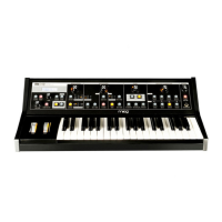
- Power up the Voyager – press the EDIT button.
- In the EDIT menu select “Init. Parameters”, press ENTER, select YES and press ENTER
again. This loads the default Voyager sound.
- Take one of your ¼” cables – plug one end into the VX-351’s LFO triangle output.
Plug the other end into the Voyager’s Filter control input.
- Play a note on the Voyager – you will hear the LFO modulating the Filter’s Cutoff.
Changing the RATE of the LFO will change the rate that the Filter cutoff goes up and
down. This demonstrates a basic patch with the VX-351. With all the CV and Gate
connections you make it is important to think of a Source (or Output), in this case
the LFO triangle wave, and a Destination (or Input), in this case the Filter Control
Input.
- Now, disconnect the cable from the Voyager’s Filter Control and connect it to the
IN of one of the Voyager’s Attenuators. Set the Attenuator amount to Zero. Take
another ¼” cable and connect it from the VX-351 Attenuator OUT to the Filter
Control Input.
- Play a note and gradually increase the Attenuator amount. You will notice that the
amount of modulation will increase. An Attenuator is used to set the amount of a
CV Source that passes to the Destination.
This is a very basic use for the VX-351 – but it shows the fundamental concept of
how to use it: source goes to destination. Using this fundamental concept, you can
patch together additional modulation – and get as complex as you like. What
follows is a detailed explanation of the output signals and the other functions
contained in the VX-351.