8 The Interface Solution Experts
SPA
2
Programmable Current/Voltage
Limit Alarm Trips
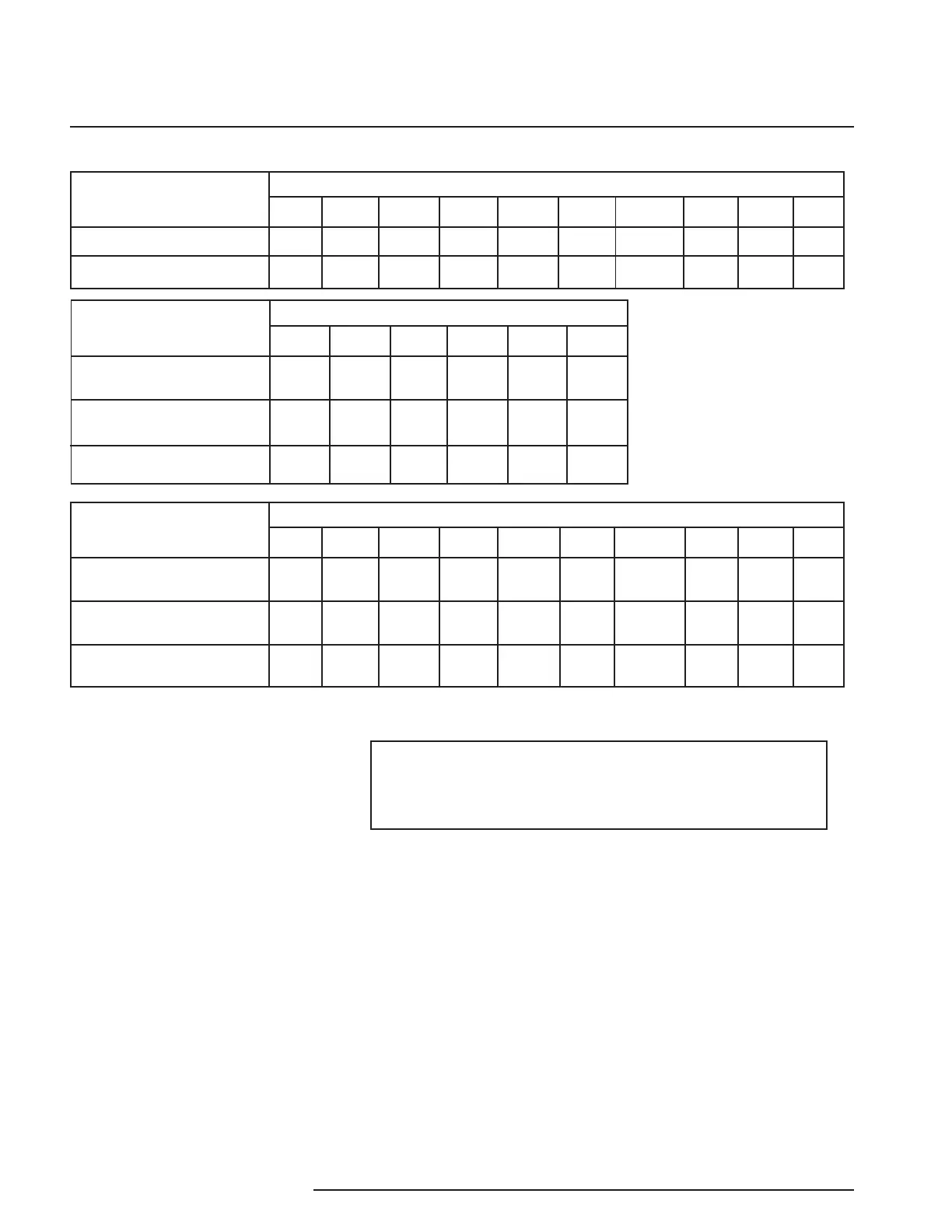
Table 2. SPA
2
(HLPRG) Terminal Designations
Input Type
Current Input
Voltage Input
Top Terminals (Left to Right)
T1 T2 T3 T4 T5 T6 T7 T8 T9 T10
KEY:
AC/DC = Power Input
ACC/DCC = Power Input
CM = Relay Common
COM = Analog Common
DPDT = Double-Pole/Double-Throw
GND = Ground
NOTES:
1. Terminal blocks can accommodate 14-22 AWG
solid wiring.
2. ±Io/±Vo labeling is present only when the unit is
equipped with the Analog Output (-AO) option.
3. Your input power requirement (AC or DC / ACC
or DCC) will depend upon your unit’s power need.
Tx
+I
COM
Not
Used
MR
MR
-Io Source
+Io Sink
+Vo
-Vo
-Io Sink
MR
-Io Source
+Io Sink
+Vo
MR
Tx
COM
Not
Used
+V
I = Current Input
Io = Current Output
MR = Manual Reset
NO = Normally Open
NC = Normally Closed
Sink = Current Sink
Source = Current Source
SPDT = Single-Pole/Double-Throw
TX = Power for 2-wire transmitter
V = Voltage Input
Vo = Voltage Output
-Vo
-Io Sink
+Io Source
+Io Source
Output Type
2PRG
(SPDT Relays)
4PRG
(SPDT Relays)
2 DPDT Relays
Middle Terminals (Left to Right)
11 12 13 14 15 16
NO3 CM3 NC3 NO4 CM4 NC4
Relay 2
CM1
Relay 2
NC1
Relay 2
NO2
Relay 2
CM2
Relay 2
NC2
Output/Power Type
2PRG
(SPDT Relays)
4PRG
(SPDT Relays)
2 DPDT Relays
Bottom Terminals (Left to Right)
B1 B2 B3 B4 B5 B6 B7 B8 B9 B10
Not
Used
AC
or
DC
ACC
or
DCC
GND
GND
N/A
N/A N/A N/A
N/A
N/A
NO1 CM1 NC1
NO2
CM2 NC2
Not
Used
Relay 2
NO1
Not
Used
GND
Relay 1
CM1
Relay 1
NC1
Relay 1
NO2
Relay 1
CM2
Relay 1
NC2
Relay 1
NO1
NO1 CM1 NC1
NO2
CM2 NC2
AC
or
DC
AC
or
DC
ACC
or
DCC
ACC
or
DCC
 Loading...