Crate HEMI® Engine Kit Instruction Sheet www.mopar.com
Rev Level 5.0 – K6862625 10
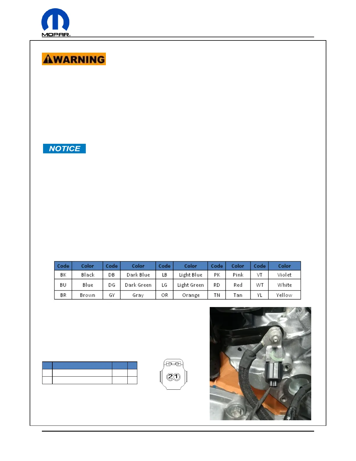
Pin Function Color GA
1 FUSED ASD RELAY OUPUT BR/YL 16
2 N0 - No Connect NA
Engine Connections
To prevent SERIOUS INJURY or DEATH:
Make sure you or the installer has the appropriate skills and the tool required to safely install
the engine.
If you do not understand the instructions, call MOPAR for assistance at 1-888-528-HEMI (4364).
Engine Harness
Each engine wiring kit will have a different number of connectors. Ensure all connectors are connected
in their appropriate location and are in the locked position. The diagrams below show all the engine and
chassis connectors. Follow wiring instructions carefully.
• Ensure the wiring harness is secured every 100 mm (4 inches) and routed to avoid potential damage to
the wiring. Make sure any unused wiring is properly secured and protected.
• Some cavities may be populated with wires however, those wires are not used in this configuration.
See pinouts for circuits used.
• All connector diagrams are in wire insertion view.
• To diagnose a wiring issue outside of this manual, use 2016 Dodge Challenger service information.
• All grounds must be clean and secure. No paint can be present between the ground and body contact
point. There are multiple grounding points on the engine and chassis side harnesses, as well as an
engine grounding cable part number 68060322AE. This part is to be fastened on one end to the engine
block and the other end to the vehicle’s chassis, there should not be tension in the Ground Jumper.
• Soldering connections and wire splicing instruction can be viewed on the final page of the wiring
section.
Capacitors
As part of the ignition system there are 2 capacitors on the
back of the engine, one on each side bolted to the cylinder
head. Plug in the connectors for both capacitors. The
capacitors have a 2 pin connector.


 To Next Page