Crate HEMI® Engine Kit Instruction Sheet www.mopar.com
Rev Level 5.0 – K6862625 17
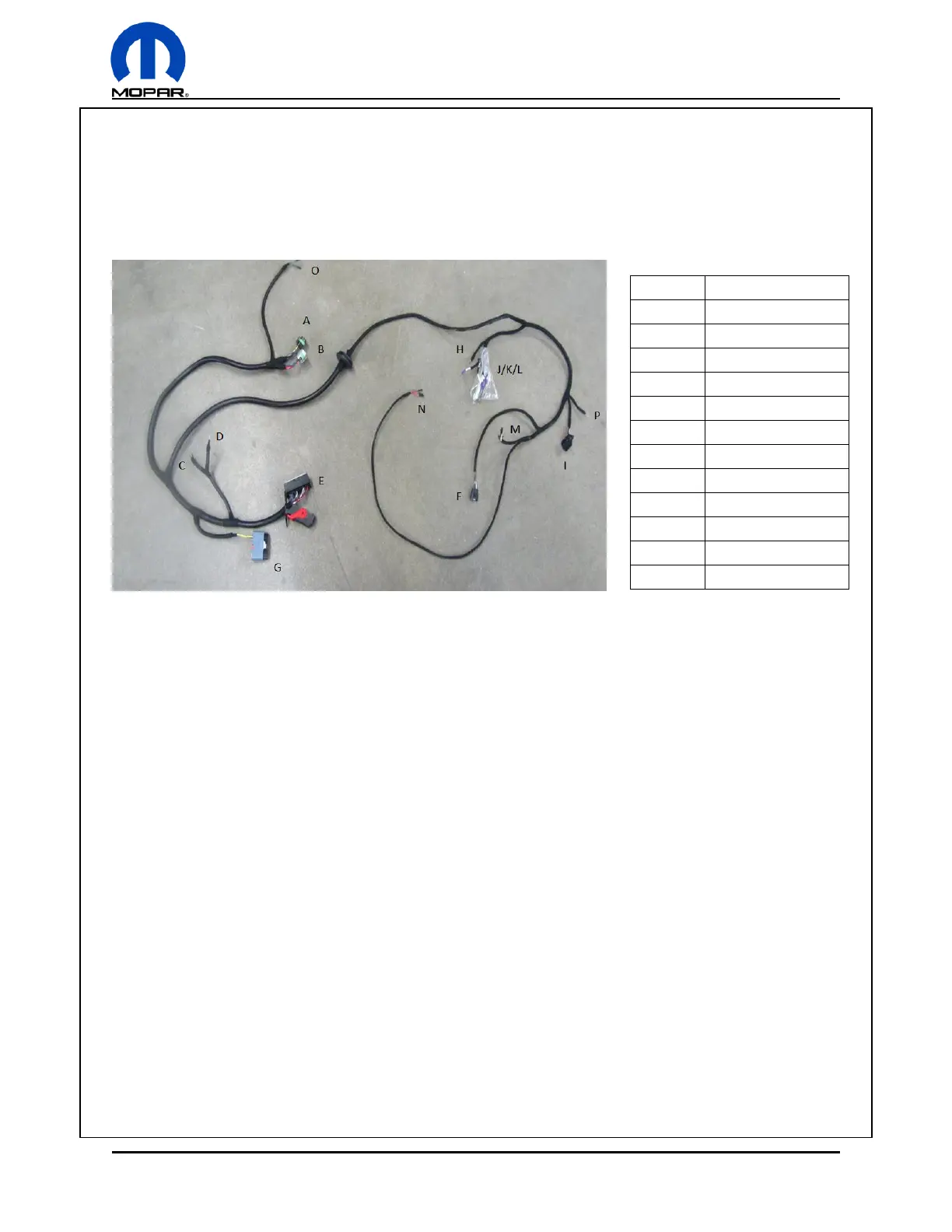
Body Harness
The body side harness consists of 2 sides, one side to route into the engine bay and mate with the PCM
and PDC, and one side to the vehicle cabin for other connections. A grommet hole of 50 mm is needed
in the bulkhead to route the harness. Ensure the hole that is cut is on a flat plane of a minimum material
thickness to seal of 5 mm and is deburred. Feed the harness through the hole and insert the grommet in
place.
Dash / Blunt Leads
Each blunt end will require the correct corresponding connection on the vehicle.
M – All Colors – Gateway: Not used in this application. (CAN Bus blunt leads)
N – Color: LB/TN – Gauge: 20 – Starter Relay Control: Connect to 12V source provided only when in
crank position. Requires a 12V input from ignition switch to control the starter relay only when key is in
the crank position.
N – Color: PK/BR – Gauge: 20 – IGN Relay Control: Connect to 12V source provided when in crank and
run position. Requires a 12V input from ignition switch to control the ignition relay when key is in the
crank and run position.
N – Color: DG/OG – Gauge: 18 – Clutch Interlock: Connect to ground input from clutch pedal switch or
neutral safety switch.
N – Color: RED – Gauge: 18 – Aux: Positive output for an auxiliary device. (12V output, 20A fuse)
O – Color: DB/OG – Gauge: 16 – Fuel Pump Feed: Positive output for an electric fuel pump. (12V output,
20A fuse)
O – Color: DG/RD – Gauge: 12 – Cooling Fan Feed: Positive output for an electric cooling fan. (12V
output, 30A fuse)


 To Next Page