10
3.e Water connection
Connect the water heater to the water supply.
From the front, the cold water input is on the right and the hot water output is on the left.
Insert the lter into the water valve input tting.
Remove the plastic cap from the water outputs tting before connecting it to the water supply.
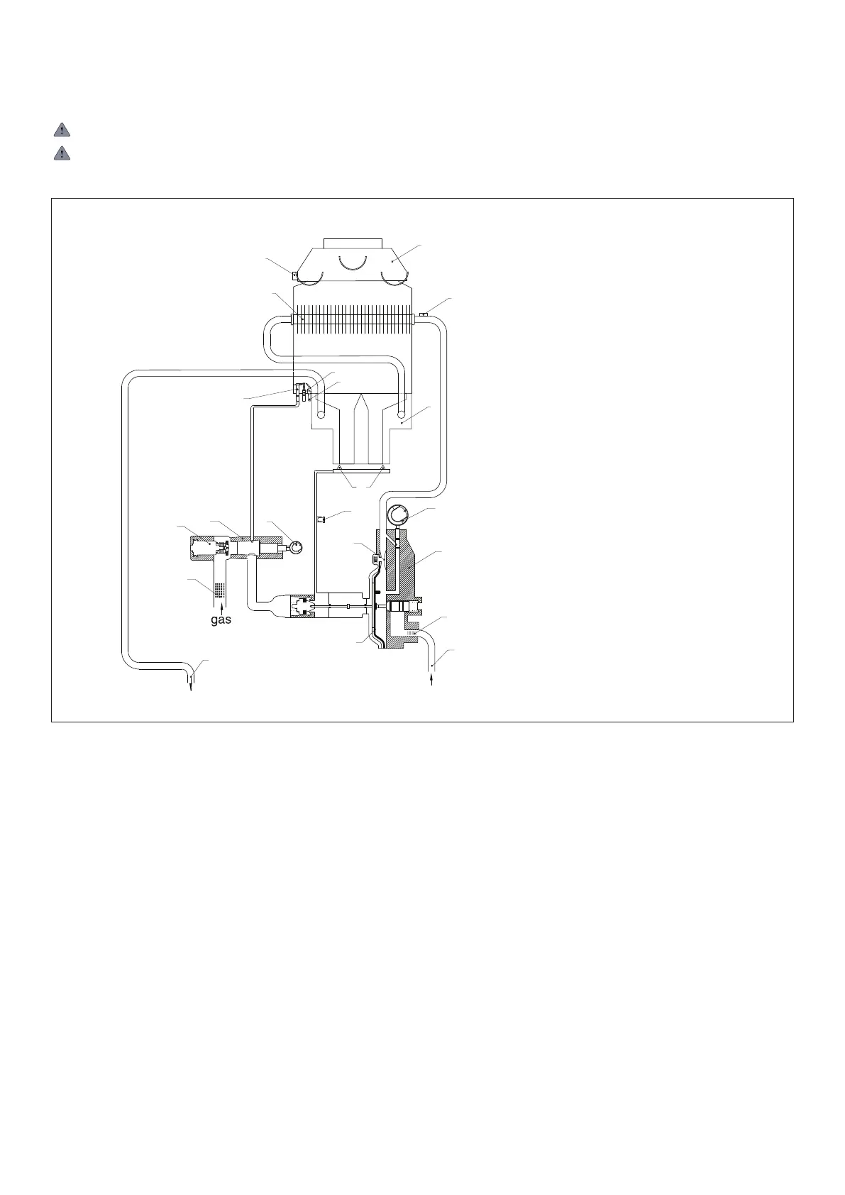
g. 5
1 Flue diverter hood
2 Flue gas safety device
3 Hot water limit thermostat
4 Heat exchanger
5 Burner
6 Ignition electrode
7 Thermocouple
8 Pilot burner
9 Main burner injectors
10 Hot water output
11 Burner pressure test point
12 Water temperature selector knob
13 Venturi
14 Water control assembly
15 Magnetic valve
16 Water lter
17 Diaphragm
18 Cold water input
19 Gas adjustment knob
20 Gas valve
1 Cappa scarico
2 Dispositivo di controllo fumi
3 Termostato limite acqua
4 Scambiatore di calore
5 Bruciatore
6
7
Bruciatore pilota8
Elettrodo di accensione
9 Iniettore
10
Uscita acqua calda
11
Presa di pressione
12
Selettore di temperatura
13
Venturi
14
Valvola idraulica
16
Filtro dell’acqua
17
Membrana
18
Entrata acqua fredda
19
20
Valvola gas
Magnete
Comando gas
Termocoppia
19
20
21
6
7
8
15
1
2
3
4
5
9
10
11
12
13
14
16
17
18
3.f Flue Gas
For output of ue gases refer to the regulations in force including
any updates. See page 3.
The water heater must be connected to a suitable ue terminal.
The following must be observed:
- The ue must be installed vertically – through the roof of the
holiday home
- The diameter of the ue terminal must match that of the water
heater (90 mm for EUP6 and 110mm for EUP11)
- The overall ue length from the top of the water heater to the
top of the external ue must be at least 600mm. The distance
from the external roof surface to the top of the external ue
must be at least at least 250mm.
Flue gas safety device
This product is equipped with a ue gas safety device. The devi-
ce ensures the ue gases leave the water heater safely via the
ue. The ue safety device marked as 2 in Fig.6 is a ue gas
safety device that will interrupt the ow of gas to the water heater
burner and pilot light in the event that there is a total or partial
blockage in the ue that does not allow the ue gases to leave
safely. The device will also operate if the design or length of the
ue is not correct. This stat will reset when it has cooled down
due to the technical issue being resolved thus allowing the water
heater to operate as normal.
If the ue gas safety device is faulty it will need to be replaced
before the water heater will function again. The stat must not be
removed or altered in any way otherwise the operation of the
water heater may become dangerous.
SCHEMATIC DIAGRAM