21
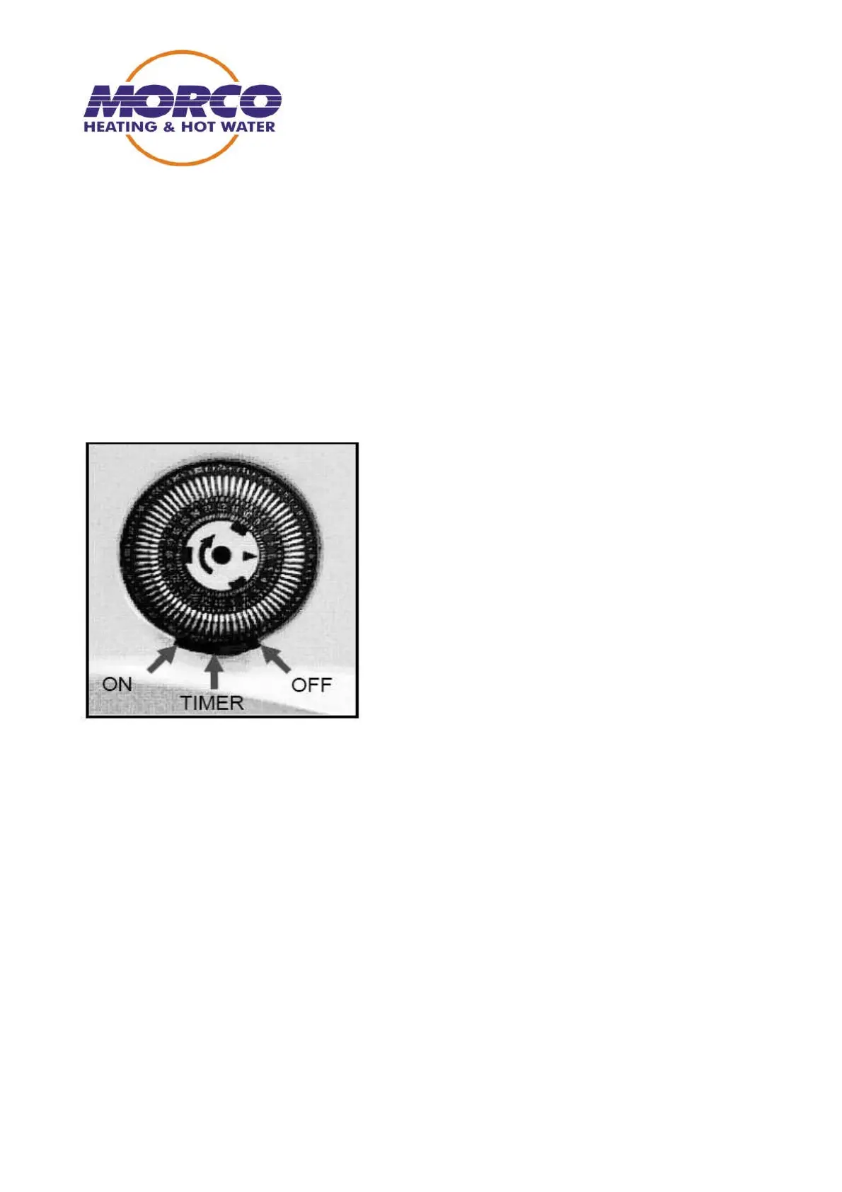
30. TIME CLOCK
Two different types of time clocks have been fitted to the boiler serial
numbers 050512656 onwards have a basic time clock without an override facility, and rely
on the tappets on the clock to be in the outward position for the heating to work.
Later models incorporate a clock with a built in override switch.
POSITIONS OF THE SWITCH ARE AS FOLLOWS
1. Switch to the left overrides timed positions and heating is on constant.
2. Switch in the centre position heating is on or off according to tappet timed positions on
the clock
3. Switch to the right heating is off.
The clock has 2 power supplies. A 230V ac supply from the electrical filter to drive the
motor within the clock. The second supply is the low voltage switching supply for the
heating demand.
Supply voltage to the clock switching circuit is fed from J4 22V dc (left hand black) via the
room thermostat connector block to the micro switch on the clock. (Contact number 4)
When the contacts in the clock are in the closed position (heating on) voltage is returned
from the clock (contact number 1) to the PCB J4 12V dc (right hand black).
N.B. All the connection terminals on the clock are of the same type DO NOT allow the
230V ac motor supply to enter the low voltage circuit which are clearly marked 1 and 4 on
the micro switch.
Remember to isolate the boiler at mains supply before working on clock, as power is
permanent regardless of the position of the on / off switch.