20
MORDAX : DATA
User Guide
SYS V. 01.00.00
BOOT V. 01.00.00
Updated: 161229
Program : Clock Output
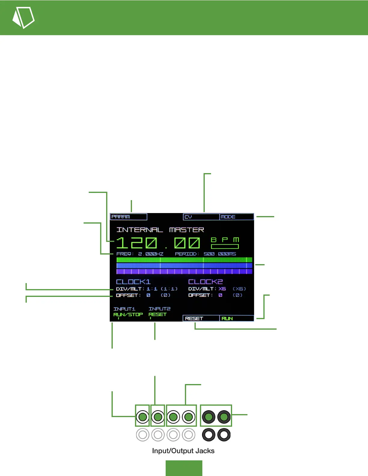
Clock - Internal Master Mode - Display Overview
PARAM: Push to scroll and
act on available main screen
parameters (e.g., Master BPM,
Clock 1 & 2 div/mult, offset)
CV: Push for the CV pop-up menu and
assign the CV source and attenuation
amount for either clock’s div/mult and
offset modulation.
MODE: Push for the Mode
pop-up menu, choosing either
INTERNAL MASTER mode or
EXTERNAL SYNC mode.
BPM: Decimal quarter note
beats per minute of the
base clock generator.
DIV/MLT: Division or multiplication
of the base clock frequency to be
output. Setting to 1:1 produces
quarter notes, and x4 gives 16th
notes (PPQN 4). Final DIV/MTL
value, adding CV inuence, is shown
to the right in grey in parentheses.
OFFSET: Output clock’s shift +/- 96
ticks (one quarter note) from the
base clock. Final OFFSET value,
adding CV inuence, is shown to the
right in grey in parentheses.
FREQ & PERIOD Display: The
frequency (Hz) and period (ms) of
the base clock generator.
Beat Displays: The top track
shows clock generator base
quarter notes, with the CLOCK1
(blue) and CLOCK2 (purple) tracks
showing their relative beat output
(divided/multiplied and offset)
INPUT1 - RUN/STOP: Indicates
the function of INPUT1. Send a
gate signal to toggle RUN/STOP
of the clock generator (same as
pushing soft button 1-4).
RUN/STOP: Push soft
button 1-4 to toggle RUN/
STOP of the clock generator.
INPUT2 - RESET: Indicates the function of
INPUT2. Send a gate signal to reset the clock
generator’s measure position (applies to longer
division settings). This has the same effect as
pushing soft button 1-3 RESET.
RESET: Push soft button 1-3
to reset the clock generator’s
measure position (applies to
longer division settings).
CV Control: Input channels 3 & 4 can be
assigned control over either clock’s div/mult
or offset parameters
Clock Out: Clock 1 and 2 output, 5V
peak-to-peak (0V to +5V) trigs
The DATA’s Clock program provides two CV controlled Clock trigger outputs, which can be driven by either the highly stable,
BPM dened Internal Master clock, or can be synced to an external clock source (External Sync Mode). Each Clock output
rate is a multiple (DIV/MULT parameter) of the Internal Master or External Sync clock and can be offset in time from the source
clock up to one quarter note forward or backwards.
The DATA’s Clock outputs can be used to trigger external sound generators directly (e.g., drum voices), acting as trigger
sequencers, or they can be used as variable clock sources to drive step sequencers or other time-based modules in
your system. With the use of CV modulation over the output clock parameters, very complex rhythms are possible, from
mechanical ratcheting to African-style drumming.
 Loading...