Do you have a question about the Morningstar Sunlight SL-20 and is the answer not in the manual?
Manual contains important installation and maintenance instructions.
Lead acid batteries can generate explosive gases and short circuits.
Do not exceed controller voltage or current ratings; use only 12V or 24V batteries.
Short-circuiting PV array or load connected to controller will damage it.
Negative system conductor must be properly grounded according to local codes.
Controller is shipped for SEALED batteries; remove jumper for FLOODED.
Ground negative system conductor for surge protection per UL recommendations.
Rated for 12V/24V PV systems; max PV open circuit voltage 30V/50V; max array current 12.5A/25A.
Controller protected from reversed connections, but system and equipment are at risk.
Step-by-step guide for connecting system components.
Confirm Solar array and loads do not exceed Sunlight controller current ratings.
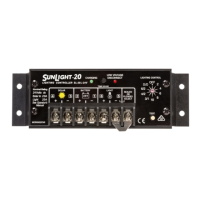
Follow label order 1 to 6; BATTERY must connect before SOLAR.
Connect 12V/24V battery; red LED indicates low charge state.
Connect solar array to SOLAR terminals; green LED confirms sunlight and correct wiring.
Connect light to LIGHT terminals; TEST button turns light on.
Jumper sets controller for SEALED batteries; remove for FLOODED batteries.
Select desired lighting control option using the rotary switch.
Test button confirms settings, turns lights on for 5 min, or tests LVD.
Advanced series PWM charge control for constant voltage battery charging.
Load disconnects below 11.7V/23.4V, reconnects at 12.8V/25.6V.
Troubleshooting by qualified personnel only; battery shorting is dangerous.
Check LED, battery type, connections, PV voltage, load, voltage drops, battery condition.
Check operating conditions, temperature compensation, battery type, connections, and controller damage.
Check TEST button, load status, fuses/breakers, connections, LED indications, PV array, battery voltage.
| Type | PWM |
|---|---|
| Rated Current | 20A |
| Operating Temperature | -40°C to +60°C |
| Load Current | 20A |
| Display | LED indicators |
| Input Voltage | 12V/24V |
| Maximum Battery Voltage | 30V |
| Self Consumption | 10mA |
| Enclosure | Plastic |
| Protection | Short circuit, reverse polarity |