SECTION 2
13
Checking Impedances
LEAD CHECK is the first option displayed on the LCD screen after patient hookup and is a valuable tool for
verifying and optimizing signal quality before starting a patient session.
From the main menu, use Down or Up/Right to scroll to LEAD CHECK. Press Enter to select.
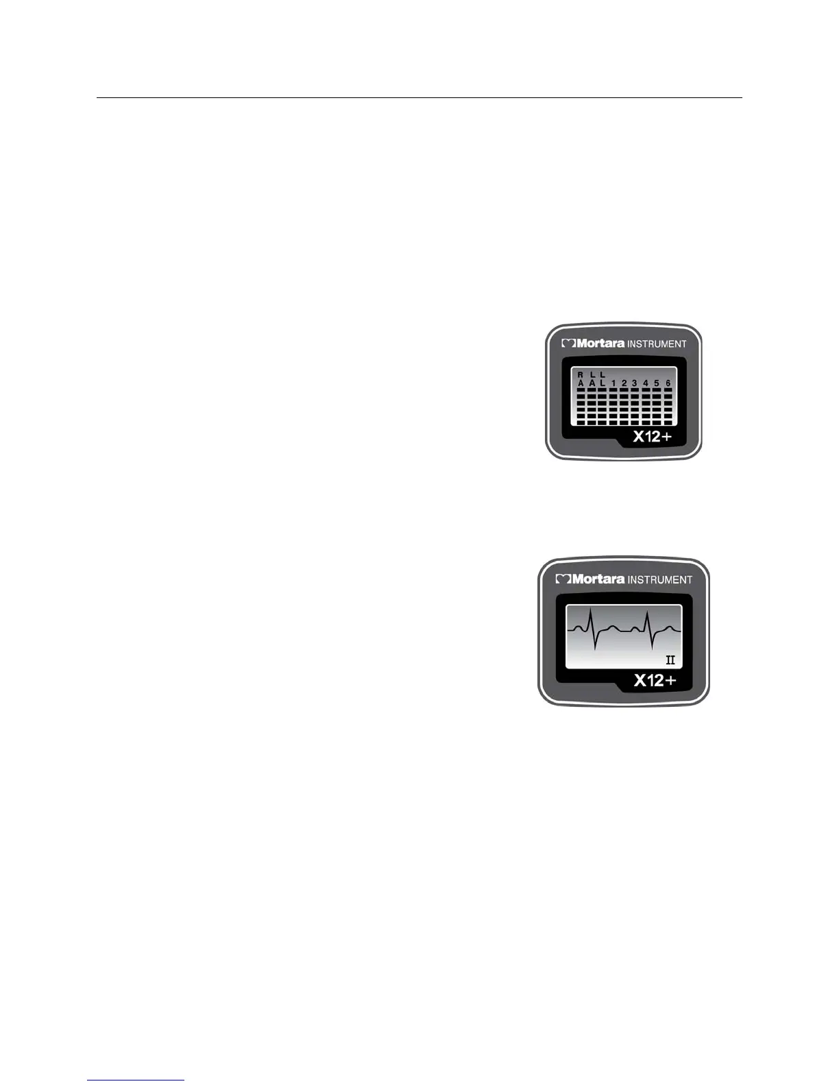
A graph depicting the impedance measured at the right arm (RA), left arm (LA), left leg (LL), and V1 through V6
electrodes is displayed from left to right in vertical columns on the screen. The higher the bar, the better the skin-to-
electrode contact.
For good quality transmissions, the bars should be at least 4 bars high.
A full-bar graph (6 bars) means optimal high quality and good
electrode contact. A low-bar graph means poor quality and high
electrode impedance. Skin preparation should be checked for
improvement and, if necessary, the electrode(s) should be replaced.
Once acceptable impedance levels are verified, press any of the three
keys to return to the top level menu.
Displaying ECG Leads
DISPLAY ECG is used to visually inspect leads I, II, III, V1, V2, V3, V4, V5, and V6 before starting a
transmission session. Check the signal quality and lead amplitude for each lead.
From the main menu, use Down or Up/Right to scroll to DISPLAY
ECG. Press Enter to select.
Lead I is the first lead displayed on the screen. Use Down or
Up/Right to scroll from lead to lead.
After visual verification of all leads, press Enter to return to the top
level menu.
Use Down or Up/Right to scroll to Exit. Press Enter to return to the
main menu.
Configuring the X12+
CONFIGURE is used to set the channel number, the number of patient cable lead wires, and the language defaults.
This menu is also used to display the software version number and current battery voltage. Settings are typically set
before the initial patient session and do not need to be set on a per patient basis.
From the main menu, use Down or Up/Right to scroll to CONFIGURE. Press Enter to select.