10
Mortonr Water Softener Installation & Operation Manual
INSTALLATION STEPS, continued
" If making a soldered copper installation, do all
sweat soldering before connecting pipes to the
softener fittings. Torch heat will damage plastic
parts.
" When turning threaded pipe fittings onto plastic
fittings, use care not to cross --thread.
" Use pipe joint compound on all external pipe
threads.
" Support inlet and outlet plumbing in some man-
ner (use pipe hangers) to keep the weight off of the
valve fittings.
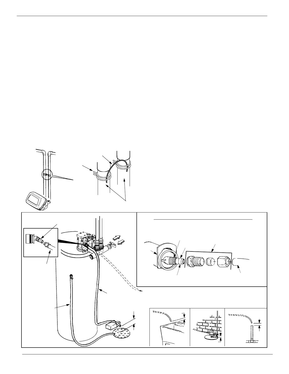
5. INSTALL GROUNDING WIRE (IF NEEDED):
" To maintain electrical ground continuity in the
house cold water piping, install a #4 copper wire
across the removed pipe section, securely clamping
it at both ends (see Figure 2) -- parts not included.
FIGURE 2
ground wire
inlet -- outlet
pipes
hose clamp
ground (2)
6. CONNECT AND RUN THE VALVE DRAIN
HOSE:
" Measure, cut to length and connect the 3/8” flex-
ible drain hose (provided) to the valve drain fitting.
Use a hose clamp to hold the hose in place.
NOTE: If codes require a rigid drain line, see “Con-
necting a Rigid Valve Drain Tube” in Figure 3.
" Locate the other end of the hose at a suitable
drain point...floor drain, sump, laundry tub, etc.
Check and comply with local codes.
IMPORTANT: If a longer length of hose is needed,
buy and use high quality, thick--wall hose that will
not easily kink or collapse. The water softener will
not work if water cannot exit this hose during regen-
erations.
" Tie or wire the hose in place at the drain point.
Water pressure will cause it to whip during the back-
wash and fast rinse cycles of regeneration. Also pro-
vide an air gap of at least 1--1/2” between the end of
the hose and the drain point. An air gap prevents
possible siphoning of sewer water, into the softener,
if the sewer should back up.
" If raising the drain hose overhead is required to
get to the drain point, do not raise higher than 8’
above the floor. Elevating the hose may cause a
back -- pressure that could reduce brine draw during
regenerations.
continued
CONNECTING A RIGID VALVE DRAIN TUBE
FIGURE 3
STANDPIPE
SUMP
LAUNDRY
TUB
1--1/2”
air gap
1--1/2”
air gap
1--1/2” air gap
To adapt a copper drain tube to the softener, buy a compression fit-
ting (1/4 NPT x 1/2”O.D. minimum tube) and needed tubing from
your local hardware store.
1/4” NPT thread
barbs
1/2” outside diameter
copper tube
Clip
Cut barbs from valve drain elbow (pull clip
and remove drain valve elbow from valve)
Compression fitting 1/4 NPT x
1/2” O.D. tube
To standpipe, sump,
laundry tub or other
approved drain.
valve drain
hose
drain fitting
adaptor
PUSH IN
for bypass
PULL OUT
for soft water
‘‘service’’
1--1/2”
air gap
FLOOR DRAIN
overflow
drain hose
valve drain
hose