9
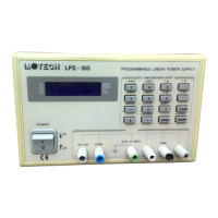
STATUS ANNUNCIATORS
Position 1: Indicator of CV mode or CC mode of + output (positive).
It will flash when the output is enabled.
Position 2: Indicator of CV mode or CC mode of - output (negative).
It will flash when the output is enabled.
Position 3: Indicator of the independent mode or tracking mode.
Flashing cursor implies the unit is working normally.
Position 4: Indicator of the selected output 5V or 3.3V.
It will flash when the output is on.
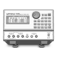
ALPHANUMERIC LCD DISPLAY
Normally LCD panel displays the preset or measured output voltage and current for both channels.
When operating at the front panel, the programmed functions (e.g. + Vset, - Iset…etc), and The preset
values (e.g. + Vset = 10.00V) will be displayed. Error conditions are also displayed on the LCD panel.
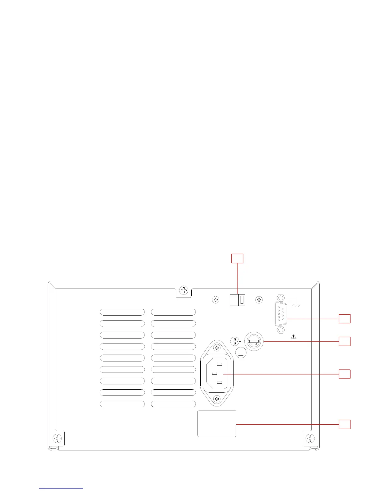
3.3 Rear panel
REFER TO FIGURE C.
(1) Input AC socket : AC receptacle for power cord
(2) Fuseholder : Fuseholder for line fuse
(3) RS-232C interface : 9-pin female DCE interface
(4) Label : Indicator of input power requirements and fuse rating.
(5) Voltage Selector :115Vac or 230Vac,-10%~+10%,50/60Hz