headline bars
tabs
continuation tabs
notes
warnings
8
GETTING STARTED
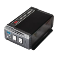
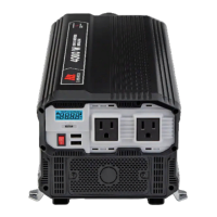
LCD DIAGRAM
Battery Level.
Output Wattage (W) or Input Voltage
Display (VDC).
Warning Indicator:
a. High voltage
b. Low voltage
c. Voltage overload
Temperature Shutdown.
1
2
3
4
3
4
1
2
Remote Instructions
The included remote control features an
LED indicator showing on/off light, push
button and 20' (6 m) cable that simply plugs
into the inverter.
Features
A: LED indicator
B: Push button
Indicator
Solid Green: Inverter “on”
No Colour: Inverter “off”
A
B
model no. 011-2102-0 | contact us 1-888-942-6686
 Loading...