90-MM6900 4
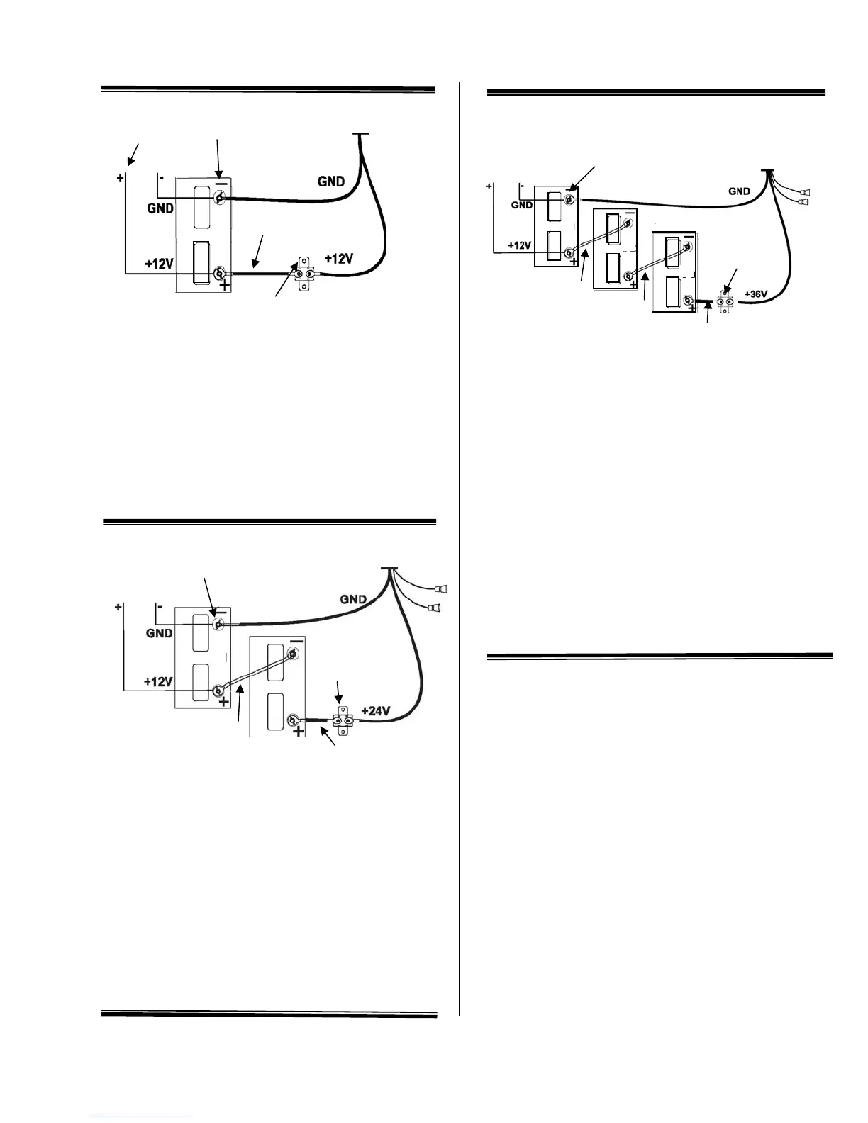
12 Volt Battery Hook-up
A) Black battery lead (-) D) Positive lead to main
engine, bilge pumps,
B) Red battery lead (+) aerators, accessories
C) 50 amp circuit E) Common ground
breaker F) Power cable
G) Jumper Wire
Connect the red battery lead to the battery positive (+)
post and the black battery lead to the battery negative (-)
post. Install a 50 amp circuit breaker in line with the
positive lead as shown above.
24 Volt Battery Hook-up
A) Battery A F) To foot pedal
B) Battery B (DS models only)
C) Positive lead to main G) To optional sonar display
engine bilge pumps, (sonar ready models only)
aerators, accessories H) Black battery lead (-)
D) Common ground I) Red battery leads (+)
E) Power cable J) Jumper wire
K) 50 amp circuit breaker
Connect the black battery lead from the power cable to the
negative (-) post on battery A and the red lead to the
positive (+) post on battery B. Connect a jumper wire
between the negative (-) post of battery B and the positive
(+) post of battery A. Install a 50 amp circuit breaker in
line with the positive lead to battery B as shown above.
36 Volt Battery Hook-up
A) Battery A H) To foot pedal
B) Battery B (DS models only)
C) Battery C I) To optional sonar display
D) Positive lead to main (sonar ready models only)
engine, bilge pumps, J) 50 amp circuit breaker
aerators, accessories K) Jumper wire
E) Common ground L) Red battery lead (+)
F) Black battery lead (-)
G) Power Cable
Connect the black battery lead from the power cable to the
negative (-) post on battery A. Connect the red battery
lead from the power cable to the positive (+) post of
battery C. Connect a jumper wire between the positive (+)
post of battery A to the negative (-) post of battery B.
Connect another jumper wire between the positive (+) post
of battery B to negative (-) post of battery C. Install a 50
amp circuit breaker in line with the positive battery lead as
shown above.
A
I
A
G
C
K
B
J
H
D
E
F
J
F
B
G
D
E
C
G
C
J
K
K
D
H
I
L
 Loading...