EN
22
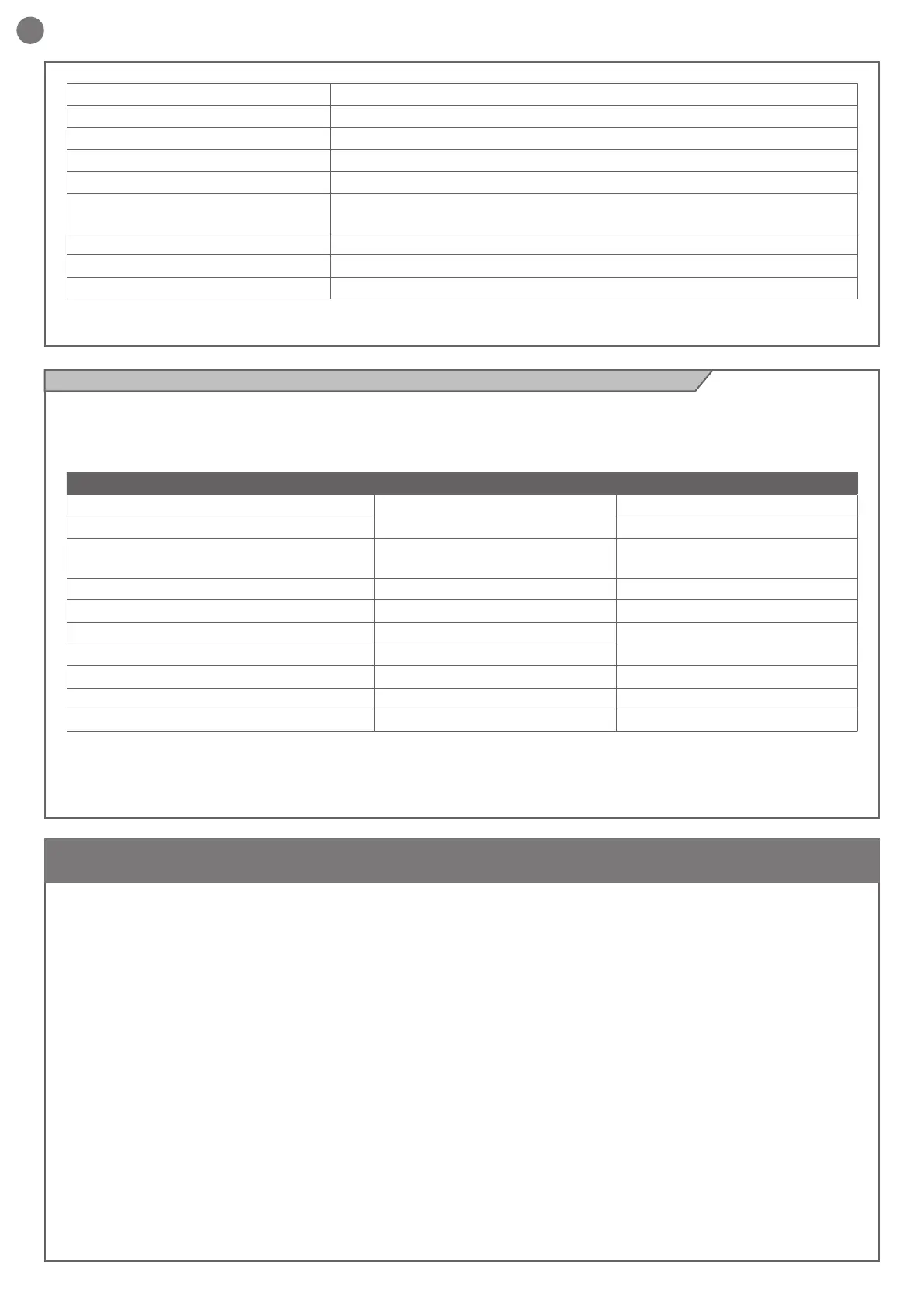
2.5 - List of cables required
Before installing this product, verify and check the following steps:
- Check that the gate or door are suitable for automation
- The weight and size of the gate or door must be within the
maximum permissible operating limits
- Check the presence and strength of the security mechanical
stops of the gate or door
- Check that the mounting area of the product is not subject to
ooding
- Conditions of high acidity or salinity or proximity to heat sources
could cause malfunction of the product
- Extreme weather conditions (for example the presence of snow,
ice, high temperature range, high temperatures) may increase the
friction and therefore the force required for the handling and initial
starting point may be higher than under normal conditions.
- Check that the manual operation of gate or door is smooth and
friction-free and there is no risk of derailment of the same
- Check that the gate or door are in equilibrium and stationary if
left in any position
- Check that the power line to supply the product is equipped with
proper grounding safety and protected by a magnetothermal and
dierential security device
- Provide the power system with a disconnecting device with a
gap of contacts enabling full disconnection under the conditions
dictated by the overvoltage category III.
- Ensure that all materials used for the installation comply with
current regulations
3 - PRELIMINARY CHECKS
ELECTRIC CABLE TECHNICAL SPECIFICATIONS
CONNECTION CABLE MAXIMUM PERMITTED LIMIT
Power line 1 cable of 3 x 1.5 mm2 20 m *
Flashing light, Courtesy light, ambient light sensor
Antenna
4 x 0.5 mm2**
1 RG58 type cable
20 m
20 m (< 5 m recommended)
Electric lock 1 cable of 2 x 1 mm2 10 m
Transmitter photocells 1 cable of 2 x 0.5 mm2 20 m
Receiver photocells 1 cable of 4 x 0.5 mm2 20 m
Sensitive edge 1 cable of 2 x 0.5 mm2 20 m
Key-operated selector switch 1 cable of 4 x 0.5 mm2** 20 m
Motor power supply line 1 cable of 2 x 1.5 mm2 10 m
Encoder power supply line 1 cable of 3 x 0.5 mm2 10 m
* If the power supply cable is more than 20 m long, it must be of
larger gauge (3x2.5mm2) and a safety grounding system must be
installed near the automation unit.
** Two cables of 2 x 0.5 mm2 can be used as an alternative
The cables required for connection of the various devices in a
standard system are listed in the cables list table.
The cables used must be suitable for the type of installation; for
example, an H03VV-F type cable is recommended for indoor
applications, while H07RN-F is suitable for outdoor applications.
Gate open warning light output 24Vdc (without regulation) 5W
Antenna input 50Ω RG58 type cable
Operating temperature -20 °C + 55 °C
Accessory fuses 2.5AT
Power supply line fuses 2AT
Use in particularly acid, saline or explosive
atmospheres
NO
Degree of protection IP54 (inside protective casing)
Control unit dimensions 183 x 102 x 59 H mm
Weight 4,3 kg