EN
21
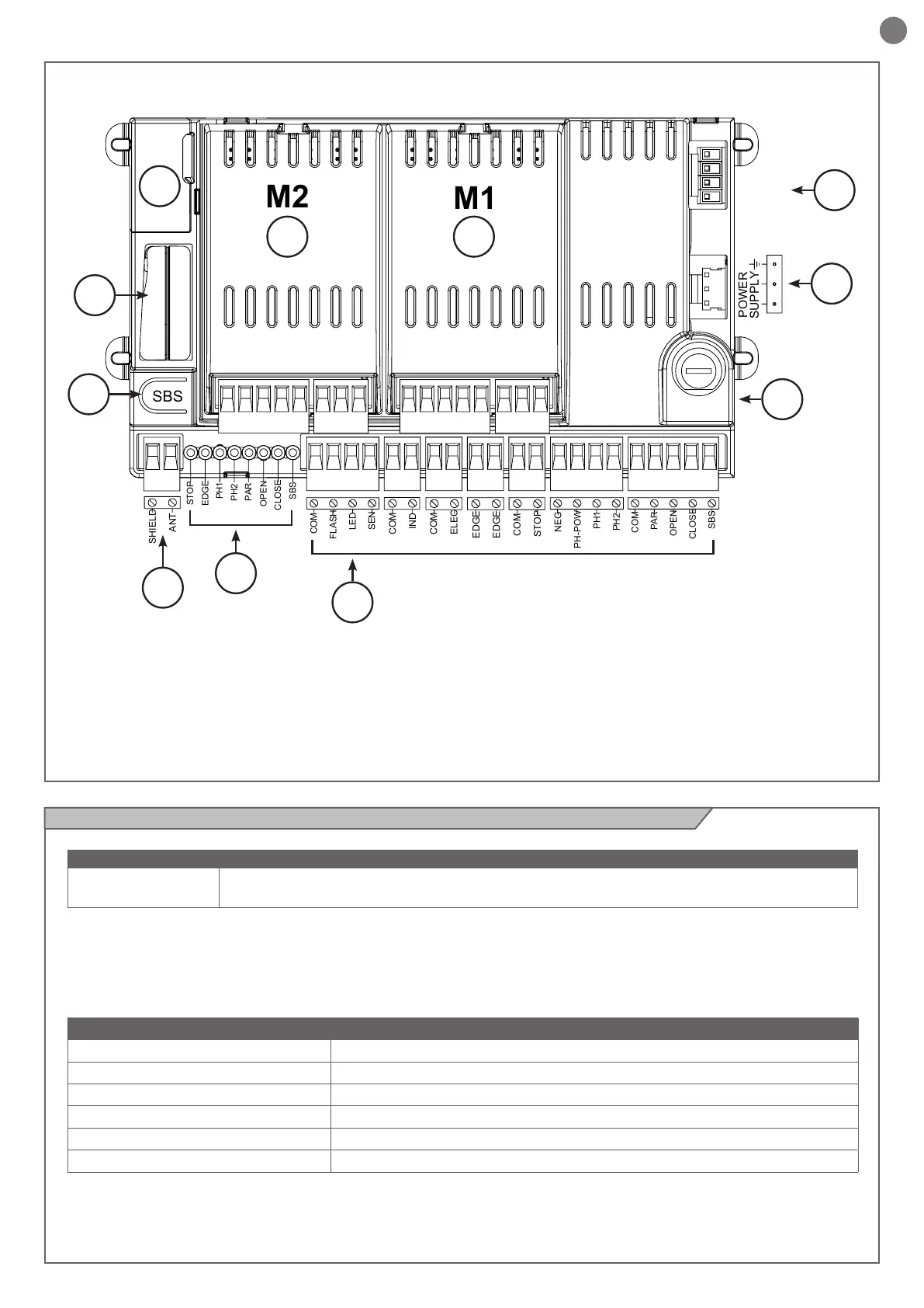
2.4 - Model and technical data of the control unit
1. Control unit power supply connection 24 Vac
2. M1 power module socket
3. M2 power module socket
4. Programmer connector / SMART
5. Receiver compartment EM4X
6. Integrated STEP BY STEP control button does the cycle
(OPEN-STOP-CLOSE-STOP)
7. External antenna connections
8. Input status indicator LEDs
9. Accessory/input connection terminal board
10. Protective fuse, 2.5AT
11. Battery connection
SBS
M1
M2
COM
PAR
OPEN
CLOSE
SBS
NEG
PH-POW
PH1
PH2
COM
FLASH
LED
SEN
SHIELD
ANT
COM
STOP
EDGE
EDGE
COM
ELEC
COM
IND
STOP
EDGE
PH1
PH2
PAR
OPEN
CLOSE
SBS
POWER
SUPPLY
23
4
6
5
7
8
9
10
11
1
BATTERIES
(ACCESSORY)
TECHNICAL DATA CC24FULL
Power supply (L-N) 230Vac (+10% - 15%) 50/60 Hz
Rated power maximum 210W
Photocell power supply output 24Vdc (without regulation) maximum 250mA
Flashing light output 24Vdc (without regulation) 25W
Courtesy light output 24Vdc (without regulation) 15W
Electric lock output 12Vac maximum 15VA
• Power supply with protection against short-circuits inside the
control unit, on motors and on the connected accessories.
• Obstacle detection by means of current sensor.
• Anti-crush safety device.
• Automatic learning of working times.
• Programmable deceleration during opening and closure.
• Safety input deactivation by means of software.
• Control panel with microprocessor logic.
Code Description
CC24
Logic module for combination with 1 or 2 power modules for the control of 1 or 2 24V motors for swing and
sliding gates