EasyManua.ls Logo

Motorline professional BRAVO500-50 - User Manual

Motorline professional BRAVO500-50
14 pages
Print Icon
To Next Page IconTo Next Page
Loading...
v4.3
REV. 05/2022
EN
USER'S AND INSTALLER'S MANUAL
EN
BRAVO500
Question and Answer IconNeed help?

Do you have a question about the Motorline professional BRAVO500-50 and is the answer not in the manual?

Summary

Safety Instructions - Overview

Attention and Compliance

General safety warnings and product compliance information.

Safety Instructions - General Warnings

General Warnings for Use

Important safety and usage information for the product manual.

Technician Safety Precautions

Specific safety precautions for installation technicians.

Safety Instructions - User and Responsibilities

User Safety Guidelines

Safety guidelines for end-users of the product.

Responsibility and Symbols Legend

Supplier liability disclaimers and explanation of manual symbols.

Package Contents

Inside Package Components List

List of components included in the product package.

Operator - Cover Access

Opening the Motor Cover

Instructions on how to open the motor cover to access internal components.

Operator - Manual Operation

Unlock Operator Procedure

Procedure to manually open the gate during power failure or damage.

Operator - Technical Specifications

Installation - Site Preparation

Site Preparation Recommendations

Recommendations for preparing the installation site for the automatism.

Create Foundation Procedure

Steps for creating a concrete foundation for the motor installation.

Installation - Foundation Mounting

Existing Foundation Installation

Procedure for installing the motor on an existing foundation.

Motor Application and Mounting

Steps for mounting the motor onto the fixing plate.

Installation - Steel Gear Rack

Steel Gear Rack Mounting

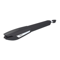
Instructions for installing the steel gear rack onto the gate.

Installation - Nylon Gear Rack

Nylon Gear Rack Mounting

Instructions for installing the nylon gear rack onto the gate.

Installation - Limit Switches

Limit Switch Plates Mounting

How to install limit switch plates on the gate rack.

Installation - Clutch Adjustment

Installation - Layout Diagram

Installation Map Overview

Diagram showing the layout of components and connections for installation.

Troubleshooting - Consumer

Consumer Troubleshooting Steps

Troubleshooting steps for end-users when the motor doesn't work.

Troubleshooting - Technician

Technician Troubleshooting Instructions

Advanced troubleshooting procedures for technicians.

Component Testing - Capacitors

Capacitor Testing Schemes

Diagrams for testing components, specifically capacitors.

Maintenance - Procedures

Routine Maintenance Schedule

Recommended maintenance procedures and schedule for the automatism.

Overview

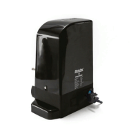
The Motorline Professional BRAVO500 is a motorized system designed for automating gates, suitable for both residential and industrial applications. This user and installer's manual provides comprehensive instructions for its installation, operation, and maintenance.

Function Description

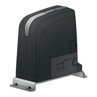
The BRAVO500 motor automates the opening and closing of gates. It is designed to provide a reliable and efficient solution for gate control, enhancing security and convenience. The system includes features for manual operation in case of power failure or malfunction, ensuring continuous accessibility. It is compatible with various accessories such as photocells, remote controls, and key selectors, allowing for flexible integration into different security and access control systems.

Important Technical Specifications

The BRAVO500 comes in two main models: BRAVO500 and BRAVO500/110, catering to different power supply requirements.

Power Supply:

  • BRAVO500: AC 230V 50Hz
  • BRAVO500/110: AC 110V 60Hz

Power:

  • Both models: 280W

Speed:

  • Both models: 0.156 m/sec

Thermal Protection:

  • Both models: 120°C

Force:

  • Both models: 1200N

Working Temperature:

  • Both models: -25°C to 55°C

Capacitor:

  • BRAVO500: 8µF
  • BRAVO500/110: 25µF

IP Protection:

  • Both models: IP44 (protected against solid objects larger than 1mm and splashing water from any direction)

Working Frequency:

  • Both models: 25%

Noise Level:

  • Both models: LpA <= 56 dB (A)

Thermal Reset:

  • Both models: 2 minutes to complete cycle

Maximum Weight of Leaf:

  • Both models: 500kg

Maximum Size of Leaf:

  • Both models: 7m

Dimensions (mm):

  • Width: 255mm
  • Depth: 186.5mm
  • Height: 319.5mm

The package includes the motor, release keys, various screws for mounting, fixation plates for the motor and limit switches, a user's manual, photocells, remote controls, and a control board.

Usage Features

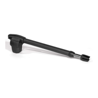
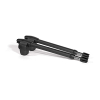
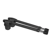
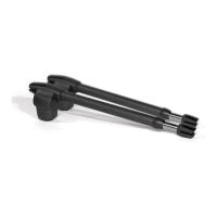
Unlocking the Operator: In case of electric power failure or damage, the gate can be opened manually. This involves:

  1. Opening the protection cover to access the keyhole.
  2. Inserting the key and turning it 90°.
  3. Pulling the lever outwards to disengage the motor, allowing manual opening/closing of the gate. To restore normal operation, the unlock mechanism must be closed, the key turned to its original position, and the protection cover re-closed. A test movement is recommended to confirm proper functioning.

Installation Site Preparation:

  • The installation requires a sufficiently resistant gate structure that is well-leveled and moves uniformly without friction.
  • A robust concrete foundation is necessary to support the mounting screws of the plate.
  • All locksmith work should be completed before installing the automatism.
  • The gate's size and weight must correspond to the motor's technical specifications.
  • A hole in the ground for the foundation should be created, with recommended dimensions of 380mm x 226mm x 385mm (height). Tubes must be left in the middle for cable passage.
  • The fixing plate is inserted into fresh concrete, leveled horizontally, and aligned parallel to the gate, maintaining a 60mm distance. The concrete must then dry completely.

Application of Motor:

  • The motor's side covers are removed to access internal components.
  • The motor is placed on the fixing plate and aligned parallel to the gate, maintaining a 63mm distance.
  • The motor is fixed with M10 x 25 screws, and the side covers are reassembled.

Installation of Steel/Nylon Gear Rack:

  • The gate must be in the open position and the motor unlocked before installation.
  • Spacers are placed in the oval holes of the rack for adjustment.
  • A piece of rack is placed on top of the pinion and leveled horizontally.
  • The spacer is welded to the gate.
  • To install subsequent rack pieces, the gate is moved slightly so the current rack piece is not supported on the pinion. A new rack piece is applied, synchronizing its teeth with the installed piece using an auxiliary rack piece and clamps.
  • The gate is opened to support the new rack piece on the pinion, and its spacer is welded. This process is repeated for each meter of the rack.
  • Manual testing of gate movement is crucial to ensure proper meshing and adjust the rack on the oval holes if friction is detected.
  • It is critical that all rack elements mesh properly with the pinion (1.5mm space). Spacers must be welded to the gate, but not the rack pieces to each other. No lubricants should be used between the rack and pinion.

Installation of Limit Switches:

  • The gate must be in the open position and the motor unlocked.
  • The opening limit-switch plate is placed on the rack to trigger the motor's limit switch before the gate reaches its physical stopper. Mechanical limit switches are activated by contact with a spring, while magnetic limit switches are activated when the magnet aligns with the motor reader.
  • DIN912 M5 x 12 screws are used to fix the limit-switch plate to the rack.
  • The process is repeated for the closing limit-switch plate after moving the gate to the closed position.
  • Limit-switch plates must be tuned to stop the gate before it hits the stoppers. Manual testing of activation with the gate unlocked is recommended before connecting to power.

Clutch Adjustment:

  • Before adjustment, disconnect power and handle the control board with care.
  • Remove the motor cover and the control board box to access the clutch adjusting screw.
  • Adjust the screw using a 6mm hexagon key.
  • Irreversibility Test: With the motor locked, try to move the gate manually. If it moves, rotate the screw clockwise (+) to increase irreversibility.
  • Idle Speed Test: If the gate does not move at idle speed, the screw is too tight. Rotate it counterclockwise (-) until the motor moves the gate at idle speed.
  • The adjustment aims for a balance between gate irreversibility and motor power. Adjustments should be made lightly, with continuous testing of motor operation.

Maintenance Features

Regular maintenance is essential for the optimal functioning of the BRAVO500 automatism. These measures should be performed every 6 months.

General Checks:

  • Inspect all screws of the automation, including those fixing the plate to the ground, the limit switch plates, the motor, and the gear rack. Ensure they are tight and secure.
  • Verify that the distance between the rack and the motor remains unchanged. This ensures correct engagement of the pinion teeth with the rack, as distortion can occur over time.

Lubrication:

  • Lubricate all systems and axes of movement of the gate.
  • Lightly lubricate the rack and pinion with spray lubricant.

Component Testing (for technicians): To diagnose malfunctions, technicians may need to test components by connecting them directly to a 110V/230V power supply, interposing a capacitor as specified in the product manual.

  • Connect power wires to the terminal.
  • Connect automatism wires to the terminal, interposing a capacitor in the opening and closing wires.
  • Once connections are complete, connect to a 110V/230V power outlet (depending on the motor/control board).
  • All tests must be performed by skilled technicians due to electrical safety risks.

Troubleshooting (for final consumers and specialized technicians): The manual provides a detailed troubleshooting guide for common issues such as the motor not working, making noise but not moving, opening but not closing, or not completing its route. This guide includes procedures for both consumers and technicians, covering checks for power supply, mechanical problems, photocell obstacles, jammed control devices, capacitor issues, and control board diagnostics using LEDs. For complex issues, it recommends consulting a qualified Motorline technician.

Motorline professional BRAVO500-50 Specifications

General IconGeneral
BrandMotorline professional
ModelBRAVO500-50
CategoryGate Opener
LanguageEnglish

Related product manuals