6 AP-7522 Access Point
1.2 Warnings
• Read all installation instructions and site survey reports, and verify correct equipment installation before
connecting the AP-7522 Access Point.
• Remove jewelry and watches before installing this equipment.
• Verify any device connected to this unit is properly wired and grounded.
• Verify there is adequate ventilation around the device, and that ambient temperatures meet equipment
operation specifications.
1.3 Site Preparation
• Consult your site survey and network analysis reports to determine specific equipment placement, power
drops, and so on.
• Assign installation responsibility to the appropriate personnel.
• Identify and document where all installed components are located.
• Ensure adequate, dust-free ventilation to all installed equipment.
• Identify and prepare Ethernet and console port connections.
• Verify cable lengths are within the maximum allowable distances for optimal signal transmission.
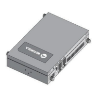
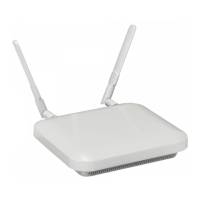
1.4 AP-7522 Package Contents
An AP-7522 Access Point is available in external antenna (AP-7522) and internal antenna (AP-7522I)
configurations. An AP-7522 ships with the following:
• AP-7522 Access Point
• AP-7522 Installation Guide (This Guide)
• Wall mount screws and mounting bracket
1.4.1 Features
An AP-7522 Access Point supports the following feature set:
• Two RJ-45 connectors (GE1/POE and Console)
• Two LED indicators
• One 2.4 GHz 802.11n radio and one 5 GHz 802.11ac radio
• 2x2 MIMO, 2 spatial streams
The GE1/POE accepts 802.3at or 802.3af compliant power from an external source
.
NOTE When operating in a Gigabit Ethernet environment, CAT-5e or CAT-6 cable
is recommended for Gigabit operation.
MN000879A01B.fm Page 6 Thursday, July 10, 2014 11:01 AM
 Loading...