Hardware Installation
5
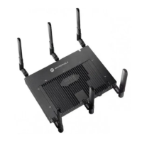
2.3.1 Antenna Options
Motorola supports two antenna suites for AP-7131 and AP-7131N models. One antenna suite
supporting the 2.4 GHz band and another antenna suite supporting the 5 GHz band. Select an antenna
model best suited to the intended operational environment of your access point. The AP-7131N model
access point can be purchased in a three radio configuration. If a three radio SKU is purchased, the
access point ships with a single antenna, factory connected, to the access point chassis (next to the
existing R1-A connector). This antenna is in addition to the other six antennas available to the access
point’s other two radios. The single antenna supporting the AP-7131N’s third radio supports sensor
mode only and can not function as a WLAN radio.
Antenna connectors for single radio model access points are located on the same side of the access
point as the LAN and WAN port connections (GE1/POE and GE2). On single radio versions, the R-SMA
connectors can support both bands and should be connected to a R-SMA dual-band antenna or an
appropriate single band antenna. If necessary a R-SMA to R-BNC adapter (Part No. 25-72178-01) can
be purchased separately from Motorola.
R1 defines the access point’s radio 1 antenna connectors and R2 defines radio 2 antenna connectors.
Certain Rogue AP Detection features use a radio to perform dual-band scanning. The dedicated radio
should be connected to an appropriate dual-band dipole antenna (Part No. ML-2452-APA2-01).

 Loading...