Hardware Installation
3
2 Hardware Installation
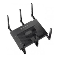
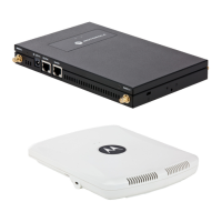
An AP-7131 or AP-7131N access point installation includes mounting the access point, connecting
the access point to the network, connecting antennae and applying power. Installation procedures
vary for different environments.
Both an AP-7131 and AP-7131N model access point have the following port designations:
• GE1/POE - LAN port
• GE2 - WAN Port
2.1 Precautions
Before installing an AP-7131 or AP-7131N model access point, verify the following:
• Do not install in wet or dusty areas without additional protection. Contact a Motorola
representative for more information.
• Verify the environment has a continuous temperature range between -20° C to 50° C.
2.2 Package Contents
Check package contents for the correct model AP-7131 and applicable AP-7131 accessories. Each
available configuration (at a minimum), contains:
• AP-7131 or AP-7131N model access point (accessories dependent on SKU ordered)
• AP-7131 Series Install Guide (this guide, supporting both AP-7131 and AP-7131N models)
• Wall mount screw and anchor kit
• Accessories Bag (4 rubber feet and a LED light pipe and badge with label for above the
ceiling installations)
Contact the Motorola Support Center to report missing or improperly functioning items.
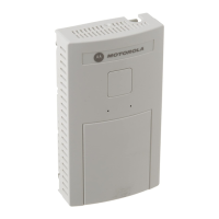
NOTE Some access points ship with a protective cover (facade) or a 6-element
MIMO antenna. The cover disconnects from the access point as
illustrated on the next page. When attached, LEDs continue to illuminate
through the cover.

 Loading...