Hardware Installation
17
8. Connect the light pipe to the bottom of the AP-7131. Align the tabs and rotate approximately
90 degrees. Do not over tighten.
9. Fit the light pipe into hole in the tile from its unfinished side.
10. Place the decal on the back of the badge and slide the badge onto the light pipe from the
finished side of the tile.
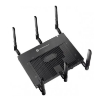
11. Attach the antennas to their correct connectors.
For information on the antennas available to the AP-7131, see
“
AP-7131 Antenna Options” on page 5.
12. Motorola recommends attaching safety wire to the AP-7131 safety wire tie point or security
cable (if used) to the AP-7131’s lock port.
13. Align the ceiling tile into its former ceiling space.
14. Cable the AP-7131 using either the Power Injector solution or an approved line cord and
power supply.
For Motorola Power Injector installations:
a. Connect a RJ-45 CAT5e (or CAT6) Ethernet cable between the network data supply (host)
and the Power Injector Data In connector.
b. Connect a RJ-45 CAT5e (or CAT6) Ethernet cable between the Power Injector Data &
Power Out connector and the AP-7131 GE1/POE port.
CAUTION Ensure you are placing the antennas on the correct connectors
(depending on your single or dual-radio model and frequency used) to
ensure the successful operation of the AP-7131.
!
 Loading...