Installation Guide 31
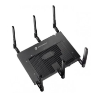
3. Position the Access Point bracket section so that the bottom of the section with the straight (not bevel cut)
sides is oriented toward the bottom side of the AP with the gore vent. Using a torque wrench or a ratchet
and a 10mm socket, or an adjustable wrench, attach (but don’t tighten) the Access Point bracket section
to the AP 7161 with the four M6 hex flange screws.
4. Insert two M6 hex flange screws into the bottom holes on the sides of the Access Point bracket section.

 Loading...