Installation Guide 15
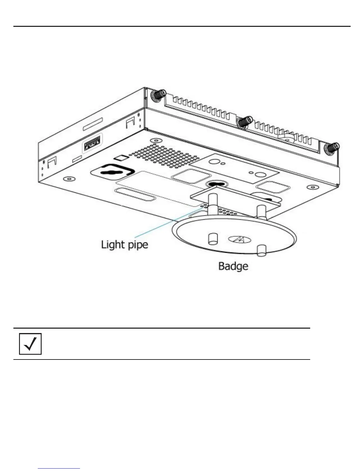
7. Remove the light pipe’s two rubber stoppers (from the access point) before installing the light pipe.
8. Connect the light pipe to the bottom of the access point. The dual channel light pipe is mated to the access
point by firmly pressing the light pipe into the two round openings that contained the two rubber plugs
removed in the previous step.
9. Fit the light pipe into hole in the tile from its unfinished side.
10. Slide the badge onto the light pipe from the finished side of the ceiling tile.
11. Attach the antennas to their correct connectors. For more information on supported AP-8132 antennas,
see
AP-8132 Antenna Options on page 17.
12. Align the ceiling tile into its former ceiling space.
13. Cable the access point using either the Power Injector solution (AP-PSBIAS-2P3-ATR) or the approved
AP-8132 power supply (PWRS-14000-247R).
For Motorola Power Injector installations:
a. Connect a RJ-45 CAT5e (or CAT6) Ethernet cable between the network data supply (host) and the
Power Injector Data In connector.
NOTE Motorola recommends attaching safety wire to the access point safety
wire tie point or security cable (if used) to the access point’s lock port.

 Loading...