6
Introduction
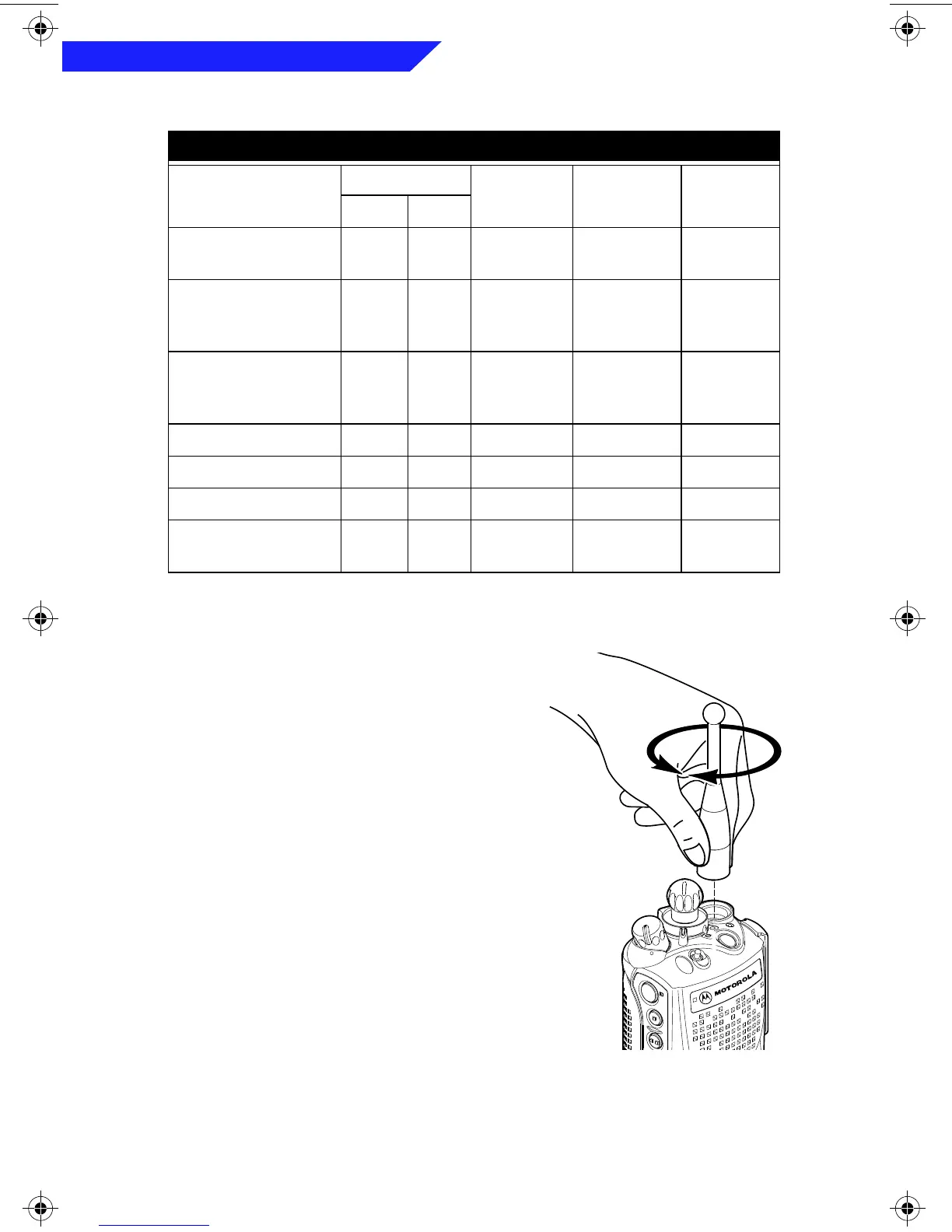
To install the antenna
, screw the threaded
end of the antenna into the antenna
receptacle on the top of the radio. Rotate
the antenna
clockwise
until it seats firmly
against the bushing.
To remove the antenna
, rotate the antenna
counterclockwise
until its threaded end
unscrews from the radio’s antenna
receptacle.
Antenna Identification Table
Antenna Type
Approx. Length
Insulator
Color Code
Frequency
Range
Antenna
Kit No.
in. mm
VHF Wide Band
Helical
8.1 203 RED 136-174MHz NAD6563
VHF Helical 7.8
7.3
6.9
195
183
172
YELLOW
BLACK
BLUE
136-151MHz
151-162MHz
162-174MHz
NAD6566
NAD6567
NAD6568
UHF Helical 3.3
3.2
3.2
83
80
79
RED
GREEN
BLACK
403-435˙MHz
435-470MHz
470-512MHz
NAE6546
NAE6547
NAE6548
UHF Wide Band Whip 5.2 130 GREY 403-512MHz NAE6549
800MHz Whip 7 175 RED 806-870MHz NAF5037
800MHz Dipole 8 200 RED 806-870MHz NAF5039
800MHz Stubby,
Quarterwave
3.3 83 WHITE 806-870MHz NAF5042
Model I Book Page 6 Wednesday, August 14, 1996 8:51 AM