October, 2004 6880309N15-A 3-5
8
9
7
6
5
4
3
2
1
11
10
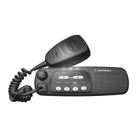
Figure 3-3. CDM Control Station
Parts List
CDM Control Station
RLN5403 Replacement Parts PL-201030-O
REFERENCE MOTOROLA
SYMBOL PART NO. DESCRIPTION QTY.
1 15-80384N52 COVER, Housing, CDM Control Station 1
2 03-12016A52 SCREW, TT3.5 x 0.6 x 6mm, Pan, Star, 10
Black Taptite
3 15-80384N55 INNER CHASSIS, Housing, CDM Control 1
Station
4 HPN9033 POWER SUPPLY with AC Line Cord 1
5 03-10907B08 SCREW, M5 x 0.8 x 8mm, Pan, Star, 2
Black, Machine
6 15-80384N52 BASE, Housing, CDM Control Station 1
7 0180305K02 ASSEMBlY, PCB, Audio Panel, CDM 1
Control Station
8 75-80384N51 KEYPAD, CDM Control Station 1
9 0180305K03 ASSEMBLY, PCB, Key Panel, CDM 1
Control Station
10 7580384N51 ASSEMBLY, Speaker 1
11 0180305K04 ASSEMBLY, PCB, Interface Module, 1
CDM Control Station
12 01-80557U01 FAN with Connector 1
13 13-83852R01 GRILLE, Fan 1
14 3080517U10 RF CABLE, Internal Mini-UHF Male to 1
“N” Bulkhead Female, 15 inches
15 42-85866M01 CLIP, Thermal Switch 1
16 30-80137S02 CABLE, Internal Radio Interface 1
17 30-82933N08 CORD, AC Line, IEC to U.S. 115 V 1
(p/o HPN9033)
non-referenced items
see note TIE WRAP, approx. 4” (not shown) 3
see note SCREW, Hex Head, 1/4-20 x 1”, Zinc 1
see note NUT, Hex, 1/4-20, Zinc 2
see note WASHER, 1/4 External Tooth, Zinc 2
see note SCREW, 4-40 x 0.25 LG, Pan, Phillips, Zinc 1
see note NUT, Hex 4-40, Plain, Zinc 7
Note: Non-referenced items cannot be ordered through Motorola, but can be pur-
chased at any local hardware store.

 Loading...