2DCX700 Quick Start Guide
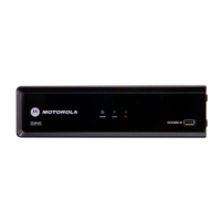
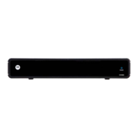
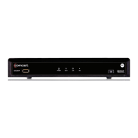
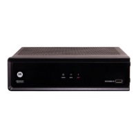
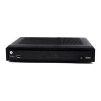
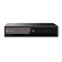
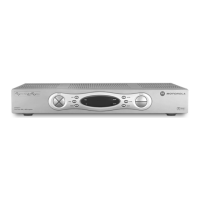
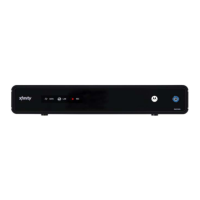
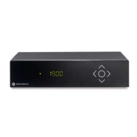
Front Panel
The front panel provides Power, Data, Home LAN, and Recording indicators, and a USB 2.0 Host Type A port. The USB connector requires the
support of application software.
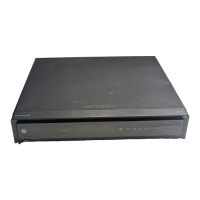
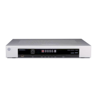
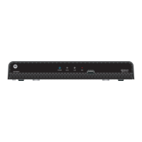
Rear Panel
The rear panel contains a power input; connectors for video, audio, and RF cabling; data output; and data interface connectors. Some
connectors are not enabled and require the support of application software.
Before You Begin
1 Power — Illuminates to indicate the power is on
2
Data — Dual function LED
• Flashes once per second to indicate unit is powering on
• Flashes once per second to indicate unit is provisioning
3
LAN — Illuminates to indicate one or more set-top boxes are detected on
the home network
4 REC — Unit is in record mode on a home network device (DCX700-M only)
5 USB* 2.0 — High-Speed peripheral device connection
6 Digital Audio (optical) — Provides Dolby
®
Digital 5.1 audio or PCM output
7 Ethernet* — Network connection
8 Ext IR Input — Connects to a remote control set-top accessory cable
9 IEEE-1394 — Audio and HDTV video device connection (US models only)
10 Power connector
POWER
LAN REC
DATA
DCX700 M-
12345
1
2
3
L
IEEE 1394
Y
Pb
Pr
VIDEO
CABLE IN
R
AUDIO
DIGITAL
AUDIO
OUT
EXT IR IN/
SERIAL
POWER
+5 VDC
61345278910
1 Cable In — Connects to the signal from your service provider
2 YPbPr — Component video output (HDTV)
3
HDMI
™
— High-Denition TV (HDTV) connector
(Provides Dolby
®
Digital Plus (7.1) audio)
4 Video — Composite Video (SDTV) output
5 Audio — Composite Audio L/R outputs
*Feature is dependent upon application support
*Feature is dependent upon application support
 Loading...