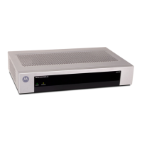
What to do if there is no video on my Motorola DSR-4550 Receiver?
D
Daniel VasquezAug 13, 2025
If there is no video or bypass video is present on your Motorola Receiver, the unit might be in bypass mode. Try changing to an available channel.
L
Lauren GonzalezAug 17, 2025
Why is there no audio on my Motorola DSR-4550 Receiver?
W
William AndersonAug 17, 2025
If there is no audio or bypass audio is present, your Motorola Receiver might be in bypass mode. To resolve this, change to an available channel.
E
Erin PerezAug 20, 2025
How to fix poor audio quality on Motorola DSR-4550?
D
Deborah TaylorAug 20, 2025
If you are experiencing poor audio quality or low audio level on your Motorola Receiver, the audio levels might be incorrect. Try adjusting the audio levels.
J
Judy MartinezAug 25, 2025
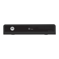
How to fix a Motorola Receiver with a blank LCD and no LEDs?
K
kgriffithAug 25, 2025
If the LCD is blank and no LEDs are lit on your Motorola Receiver, it could be due to no power to the unit. Make sure the unit is properly plugged in.
S
Stephen MorrisonAug 28, 2025
How to change the audio language on my Motorola DSR-4550?
J
Joseph MichaelAug 28, 2025
If your Motorola Receiver is displaying the incorrect audio language, it is likely due to a wrong language setting. Check the audio language settings and adjust them accordingly.
S
Scott HillSep 1, 2025
How to fix incorrect subtitle language on Motorola DSR-4550 Receiver?
I
Isabel KellySep 1, 2025
If your Motorola Receiver displays subtitles in the incorrect language, the language setting is likely wrong. Check the subtitle language settings and adjust them.
G
Gail PalmerSep 5, 2025
What to do if my Motorola DSR-4550 will not acquire signal?
T
Tony JacobsSep 5, 2025
If your Motorola Receiver will not acquire a signal, the port may not be configured correctly. Check the port configuration and manually tune the frequency.
K
Krista BriggsSep 8, 2025
Why does my Motorola DSR-4550 have no picture and no level indication?
T
Timothy KlineSep 9, 2025
If your Motorola Receiver shows no picture and no level indication, it could be due to no LNB signal port connection. Connect the LNB coax cable.