EasyManua.ls Logo

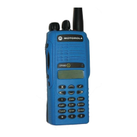
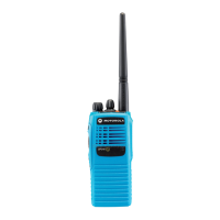
Motorola EP350

Motorola EP350
154 pages
To Next Page IconTo Next Page
Loading...
Portable Radios
Detailed Service Manual
EP350

Table of Contents

Other manuals for Motorola EP350

Questions and Answers:

Motorola EP350 Specifications

General IconGeneral
Channel Capacity16 channels
IP RatingIP54
Drop Resistance1.2 meters
Frequency RangeVHF: 136-174 MHz, UHF: 403-470 MHz
Battery LifeUp to 11 hours
Power Supply7.5 V (Nominal)
WaterproofSplashproof
Dimensions127.6 x 62 x 42 mm (with standard battery)

Summary

Safety Information

Product Safety and RF Energy Exposure Compliance

Information on product safety and compliance with RF energy exposure requirements.

Chapter 1 Maintenance

1.4 Safe Handling of CMOS and LDMOS

Precautions for handling CMOS/LDMOS devices to prevent damage from static or voltage.

1.5 General Repair Procedures and Techniques

Guidelines for performing general repairs, including parts replacement and techniques.

Chapter 2 Test Equipment, Service Aids, and Service Tools

2.1 Test Equipment

List of essential test equipment required for radio servicing.

Chapter 3 DC Power Distribution

3.1 DC Regulation and Distribution

Block diagram and description of DC power regulation and distribution.

Chapter 4 Controller Theory of Operation

4.1 RX Audio Circuit

Theory of operation for the receive audio circuit.

4.2 TX Audio Circuit

Theory of operation for the transmit audio circuit.

4.3 Microprocessor Circuitry

Theory of operation for the microprocessor and associated EEPROM.

Chapter 5 UHF2 Theory of Operation

5.2 UHF2 Receiver

Detailed theory of operation for the UHF2 receiver.

5.2.1 Receiver Front End

Explanation of the UHF2 receiver front end circuitry.

5.3 UHF2 Transmitter

Detailed theory of operation for the UHF2 transmitter.

5.4 UHF2 Frequency Generation Circuitry

Theory of operation for UHF2 frequency generation.

Chapter 6 UHF2 Troubleshooting Tables

6.1 Troubleshooting Table for Receiver (UHF2)

Table for diagnosing receiver issues in UHF2 radios.

6.2 Troubleshooting Table for Synthesizer (UHF2)

Table for diagnosing synthesizer issues in UHF2 radios.

6.3 Troubleshooting Table for Transmitter (UHF2)

Table for diagnosing transmitter issues in UHF2 radios.

6.4 Troubleshooting Table for Board and IC Signals (UHF2)

Table for diagnosing board and IC signal issues in UHF2 radios.

Chapter 7 UHF2 Schematic Diagrams, Overlays, and Parts Lists

7.3 Circuit BoardSchematic Diagram and Parts List (UHF2: 435-480 MHz)

Detailed schematics and parts for UHF2 circuit boards.

7.3.1 Parts List

Comprehensive list of electronic components for UHF2.

Chapter 8 VHF Theory of Operation

8.2 VHF Receiver

Detailed theory of operation for the VHF receiver.

8.2.1 Receiver Front End

Explanation of the VHF receiver front end circuitry.

8.3 VHF Transmitter

Detailed theory of operation for the VHF transmitter.

8.4 VHF Frequency Generation Circuitry

Theory of operation for VHF frequency generation.

Chapter 9 VHF Troubleshooting Tables

9.1 Troubleshooting Table for Receiver (VHF)

Table for diagnosing receiver issues in VHF radios.

9.2 Troubleshooting Table for Synthesizer (VHF)

Table for diagnosing synthesizer issues in VHF radios.

9.3 Troubleshooting Table for Transmitter (VHF)

Table for diagnosing transmitter issues in VHF radios.

9.4 Troubleshooting Table for Board and IC Signals (VHF)

Table for diagnosing board and IC signal issues in VHF radios.

Chapter 10 VHF Schematic Diagrams, Overlays, and Parts Lists

10.3 Circuit BoardSchematic Diagram and Parts List (VHF: 136-174 MHz)

Detailed schematics and parts for VHF circuit boards.

10.3.1 Parts List

Comprehensive list of electronic components for VHF.

Chapter 11 UHF1 Theory of Operation

11.2 UHF1 Receiver

Detailed theory of operation for the UHF1 receiver.

11.2.1 Receiver Front End

Explanation of the UHF1 receiver front end circuitry.

11.3 UHF1 Transmitter

Detailed theory of operation for the UHF1 transmitter.

11.4 UHF1 Frequency Generation Circuitry

Theory of operation for UHF1 frequency generation.

Chapter 12 UHF1 Troubleshooting Tables

12.1 Troubleshooting Table for Receiver (UHF1)

Table for diagnosing receiver issues in UHF1 radios.

12.2 Troubleshooting Table for Synthesizer (UHF1)

Table for diagnosing synthesizer issues in UHF1 radios.

12.3 Troubleshooting Table for Transmitter (UHF1)

Table for diagnosing transmitter issues in UHF1 radios.

Chapter 13 UHF1 Schematic Diagrams, Overlays, and Parts Lists

Appendix A Warranty, Service Support, and Replacement Parts

Related product manuals