12 EX-3524/EX-3548 Layer 2 Gigabit Ethernet PoE/PoE+ Switch
2.6 LED Codes
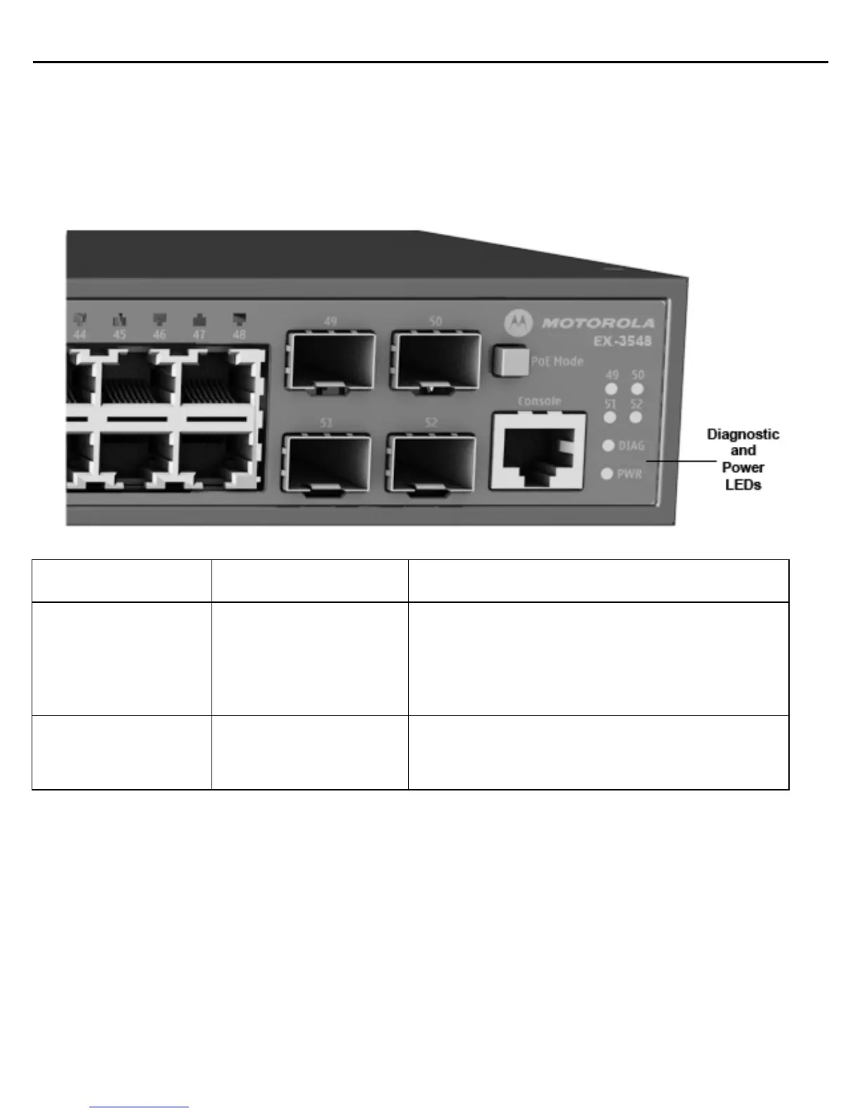
2.6.1 System Status LEDs
The diagnostic and power LEDs located on the front panel are shown below and described in the following table:
LED Condition Status
DIAG
Green Solid
Amber Solid
Blinking Amber
Blinking Amber and Green
System diagnostic test completed successfully
System diagnostic test in progress or PoE button pressed
System fault detected
System booting up
PWR
Green Solid
Off
Internal power operating normally.
No AC power is connected or the internal power supply
has failed.

 Loading...