March, 1997 68 No.
1-1
Radio Disassembly / Re-assembly
Section 1
Disassembly/Re-assembly
Radio Disassembly and Assembly
To Remove Control Head & Chassis
Covers
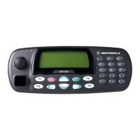
1. Remove control head mounting screws
(Figure 1-1).
2. Pull control head off and away from the radio.
3. Carefully remove control head connectors
from chassis.
4. Remove the two chassis cover screws from
each side (Figure 1-1).
5. Remove top and bottom covers from chassis.
To Remove RF Chassis Shield
Remove RF chassis shield by prying each of the four
corners at the indentations provided (Figure 1-2). Be
careful not to over bend any one corner.
To Remove the PA Heatsink
1. Disconnect the transmit and receive coaxial
cables from the RF board (Figure 1-3).
2. Disconnect the 6-pin connector from the logic
board (Figure 1-4).
3. Remove the heatsink mounting screws
(Figure 1-4).
4. Pull heatsink off of chassis while carefully
feeding the transmit and receive coax cables
through their respective holes in the chassis.
To Remove the RF Circuit Boards
1. After the PA heatsink has been removed, pry
off the RF shield (Figure 1-5). Be careful not to
over bend any one corner or side.
TOP
COVER
COVER
SCREWS
COVER
SCREWS
CONTROL
HEAD
MOUNTING
SCREWS
CONTROL
HEAD
Figure 1-1.

 Loading...