3-10 MAINTENANCE
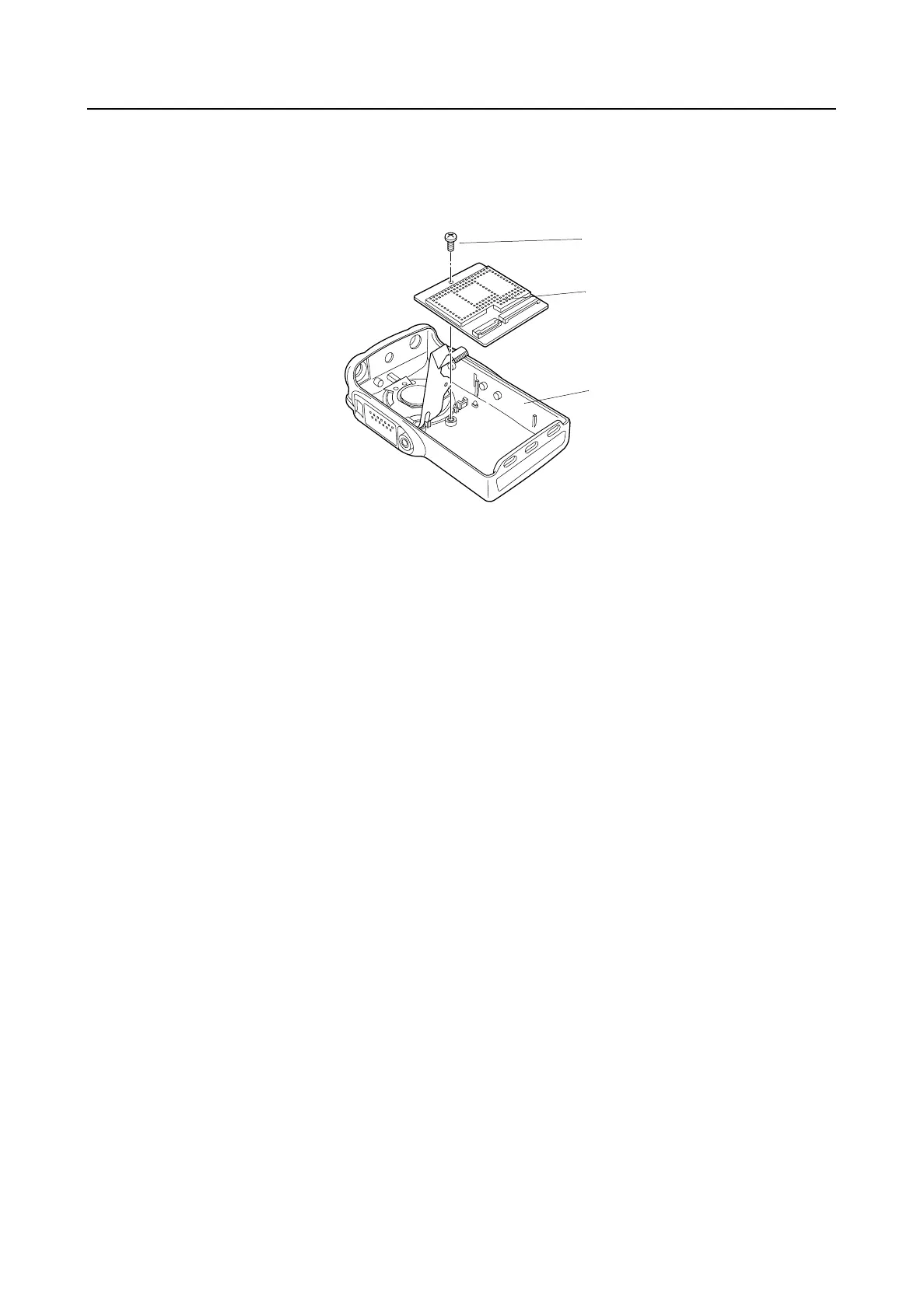
6.6 Controller Board Disassembly (GP344/GP388)
1. Use a Philips screwdriver to remove the screw from its position.
2. Insert a flat blade screwdriver in-between the controller board and front cover. Pull up the
screwdriver to disassemble the controller board from the front cover.
Figure 3-10 Controller Board Disassembly
6.7 Control Top Disassembly
1. To remove the control top assembly, place a screwdriver next to the antenna boss, and pry it
against the control top escutcheon. This will lift the control top escutcheon away from its
double-sided adhesive. Grab the double-sided adhesive near the volume potentiometer, and
lift it away.
2. Remove the control top seal, emergency button, and transmit light pipe.
7.0 Radio Reassembly — Detailed
7.1 Control Top Reassembly
1. Replace transmit light pipe and control top seal.
2. Place a new control top escutcheon adhesive against the front cover. Press the control top
escutcheon tightly against the adhesive.
3. Put the PTT seal in the PTT bezel.
7.2 Controller Board Reassembly (GP344/GP388)
1. Insert controller board into front cover and secure using the (M2x3) Philips screw.
Philips Screw
Controller Board
Front Cover
GP344/388
 Loading...