Radio Reassembly — Detailed 3-13
7.7 Chassis and Front Cover Reassembly
1. Align the chassis assembly end-to-end with the front cover assembly.
2. Insert the tails of the flex circuits into their respective connectors at the bottom of the front
cover.
3. Push down the latches on the connectors to hold the flex circuits to the main board.
4. Slide the volume potentiometer and frequency switch shafts into their respective holes in the
front cover.
5. Push the chassis assembly completely into the top of the front cover until it settles in place.
6. Be sure the O-ring is properly seated.
7. Snap the bottom of the chassis into the front cover.
8. Reassemble the knobs, dust cover, antenna, and battery.
Figure 3-12 Fastening the Chassis
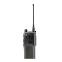
Radio Chassis
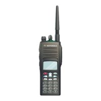
Radio Chassis
GP320/340/360/380 GP344/388
 Loading...