3-2 6880907Z66-O June, 2000
Accessory Connector Procedures GTX Mobile Radio Installation Manual
Speaker, Microphone, PTT Switch & Ignition Sense
Speaker, Microphone, PTT Switch &
Ignition Sense
Connection Procedures
Figure 3-1 shows the connection diagram of the
Speaker, Microphone, PTT Switch, and Ignition Sense
Switch.
NOTE
The mobile radio is shipped with ignition
sense disabled. To enable, slide S401-2
off.
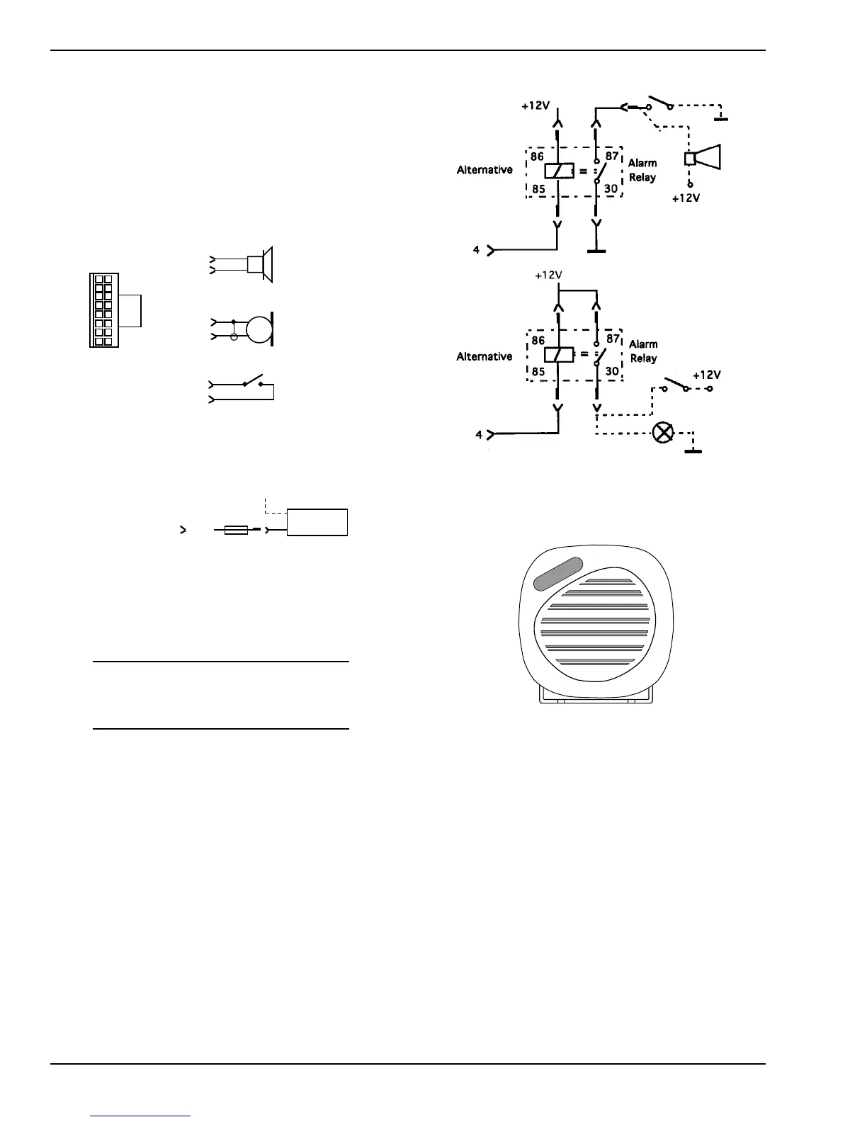
Figure 3-2 shows the connection diagram of the Exter-
nal Alarm, Relay and Cable.
Speaker
The GTX radios use a 7.5 Watt speaker. Refer to
Figure 3-3.
This speaker can be connected to the accessory connec-
tor located on the rear side of the radio between pin 1
and pin 16. Refer to Figure 3-1.
1
16
Speaker
7
2
Microphone
3
7
PTT Switch
10
Emergency
Switch
Ignition
S w itch
Ignition Sense
"on - off"
+12V
4A
16
21
15
Shown from
Figure 3-1. Connection Diagram for Speaker,
Microphone, PTT Switch, Emergency Switch,
and Ignition Sense Switch
Figure 3-2. External Alarm Relay and Cable
Figure 3-3. 7.5 Watt Speaker
 Loading...


