INSTALLATION MTM800 Enhanced Mobile Terminal Installation Manual 53
Service
The junction box PCB is not repairable. Please order a new junction box as necessary.
Connections
1. Connect all accessories to the junction box.
2. Connect the mobile-terminal-to-Junction box cable to the junction box.
3. Connect the programming cable to the junction box (if required).
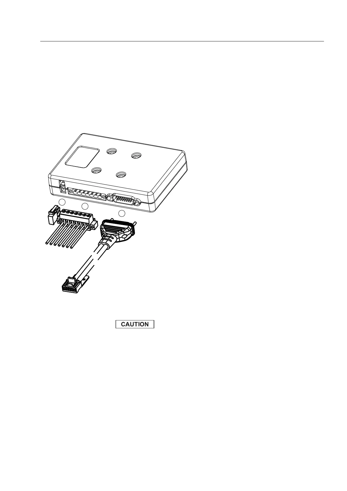
Figure 24 Connectors on the Junction Box - Front Panel
PIN 4: Use an adapter between the radio and the
accessory connector to short the ignition to ground.
Interference can cause radio to hang.
1 = Connecting cable from Junction Box
to MTM800 Enhanced (rear side
accessory connector) for installation
purpose only.
GMKN4192 (length 6 m)
GMKN4193 (length 4 m)
GMKN4194 (length 2 m)
2 = Connector for accessory terminal
pin 1 SPEAKER +
pin 2 SPEAKER -
pin 3 EXT_PTT
pin 4 IGNITION SENSE
pin 5 EXT_ALARM
pin 6 EMERGENCY
pin 7 GND
3 = Connector for visor microphone
 Loading...