of 51 GSM Field Service Support
16
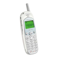
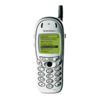
T200 / T2688
4.1 Disassembly Introduction
The T200 is held together by 4 screws. 1 of these screws should be placed under the warranty seal, on
the RH side of the phone rear facing towards you, antenna up).
Ensure that a properly grounded high impedance conductive wrist strap is used whilst performing any
tasks during the disassembly and assembly of the unit
Avoid stressing the plastics in any way to avoid damage to either the plastics or internal components.
4.2 Recommended Tools
The following tools are recommended for use during the assembly / disassembly of the T200.
• Anti-static Mat Kit - 0180386A82, includes:
Antistatic mat 66-80387A95
Ground Cord 66-80334B36
Wrist Band 42-80385A59
• Plastic Bladed Tool SLN7223A
• T6 Torx Driver
4.3 Disassembly Procedure
The following set of diagrams will demonstrate the correct sequence and action required to disassemble
the T200
The use of the exploded diagram on pages 19 may be of some assistance for part recognition.
4.4 Assembly Procedure
Once the unit is disassembled and the repair is carried out, the unit must then be reassembled, this is
carried out in the exact reverse order as the disassembly. Although the housings are put back together
parrallel to each other not ‘hinged’ apart as in disassembly.
!! CAUTION !!
Many of the intergrated devices used in this equipment are vulnerable to damage from
electro-static charges. Ensure that adequate static protection is in place when handling,

 Loading...