Motorola Confidential Proprietary
V975/V980/C975/C980Manual Test Procdures
2-4
Draft 1.0
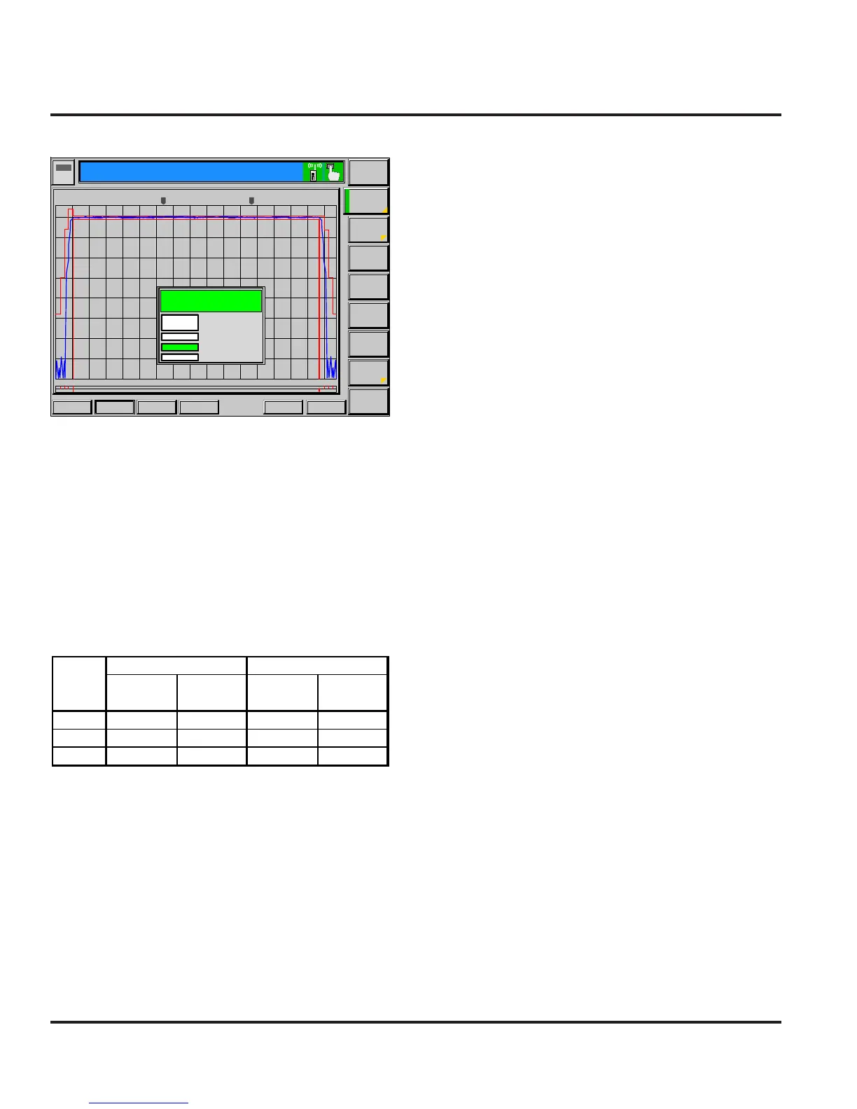
Burst Output Shape should fall within the standard lim-
its of the Power Ramp.
BER measurements is only required if RX Quality reads
a value of 4 or greater.
It is recommended that handover procedures be per-
formed as shown in the following table.
Table 2-4. GSM/DCS/PCS Handover
Traffic
Channel
Power
Control
Traffic
Channel
Power
Control
GSM 975 5 124 19
DCS 512 0 885 15
PCS 512 0 810 15
From To
Band
Figure 2-4. Burst Output Shape
Applic. 1
Applic. 2
MS Signal
BS Signal
Network
Menus
Connect
Control
P/t Norm,
GMSK
Overview
Analyzer
Level
dB Max. Level: Auto Low Noise PCL: 1 / 28.0dBm Chan. / Meas Slot: 740 / 3
R
U
N
GSM
1800 Overview
Ch. 2
Circuit
Switched
Single Slot
Ch. 1
Marker
Display
Receiver
Quality
Power Modulation Spectrum
Audio
R
---
/ Off / Off:
---
1
:
2
:/Off
---
:
+0
-10
-20
-30
-40
-50
-60
-70
-80
0 20 40 60 80 100 120 140
Current
Avg.BurstPower(Cur.)
Timing Adv.Error
TSC detected
StatiaticalCounr
Out of Tolerance
25.57 dBm
-0.75 Sym.
GSM 0
100Bursts
0.00 %
Ok
GSM/DCS/PCS Call Processing
 Loading...