CSD Series Variable Frequency AC Drive
MOTORTRONICS
- 41 -
Fn52 = Line speed display in accordance with maximum output
frequency (Fn06)
Stopping Mode
The CSD drive, after decelerating the load to zero speed applies a
small amount of DC current into the motor to bring the motor to a
final stop. The parameters of this DC injection braking capability are
defined by Fn53 - Fn55. Program Fn53 - Fn55 as required by the
application.
Fn53 = DC Braking time - Factory Setting = 0.5 sec.; Range = 0 - 25.5 sec
Amount of time the DC current is applied to the motor.
Fn54 = DC Braking Injection Freq. - Factory Setting = 1.5 Hz.;
Range = 0.1 - 10 Hz
The frequency at which, while the drive is decelerating, it will switch
from dynamic braking to DC injection braking.
Fn55 = DC Braking level - Factory Setting = 8%; Range = 0 - 20%
Defines the magnitude of the DC current and, thereby, the magnitude
of DC torque to the motor.
Multifunction Input:
The multifunction input contacts of TM2 pins 6,7 and 8 can be defined
by Fn56 to Fn58.
Fn56 defines the functionality of the multifunction digital input contact
on TM2-6.
Fn57 defines the functionality of the multifunction digital input contact
on TM2-7.
Fn58 defines the functionality of the multifunction digital input contact
on TM2-8.
Note: When it is discussed “Programming this function...” Fn56-58
is the reference.
Note: Changing these functions to 00-15 has normally open (N.O.)
contacts or changing to 16-31 has normally closed (N.C.) contacts.
Fn56 - Fn58 = Programming this function with the following:
00/16: SP1 (Multispeed 1): Refer to Fn17
- defines this terminal as a preset speed switch #1
01/17: SP2 (Multispeed 2): Refer to Fn17
- defines this terminal as a preset speed switch #2
02/18: SP3 (Multispeed 3): Refer to Fn17
- defines this terminal as a preset speed switch #3.
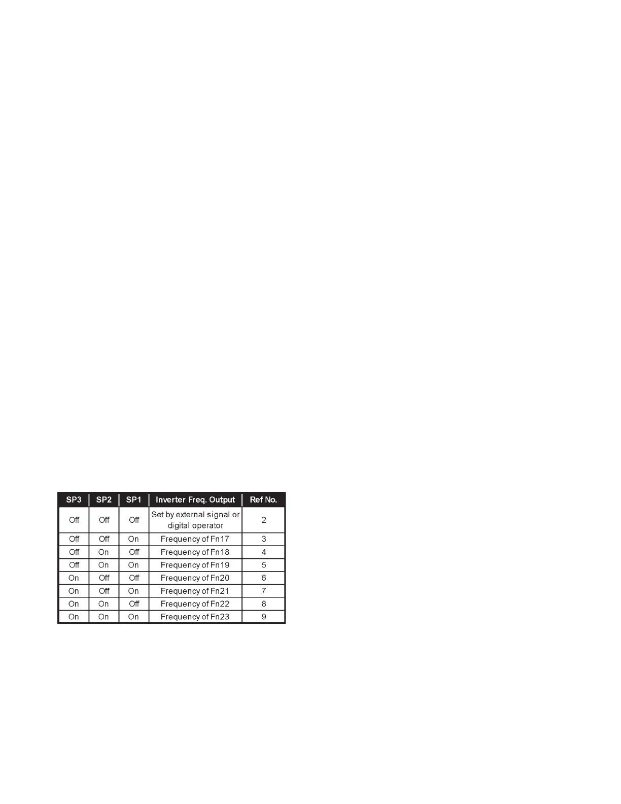
By programming these terminals as preset speed contacts, the drive
can be run at up to seven different speeds depending on the switch
position. Example: Function 56 = 00, 57 = 01 and 58 = 02. For more
information, review page 32 for Fn17 - Fn23. This table represents the
output of the drive for various switch combinations:
03/19: Jog operation: Refer to Fn17
Defines this terminal as a jog speed switch. By programming one of
the multifunction switches as a jog contact, it can be used to force
the output frequency to the value in Fn24.
04/20: Accel/Decel time selection: Refer to Fn01 - point 2Defines this
terminal as a second accel/decel time switch. By programming one
of the multifunction switches as second accel/decel time switch the
customer can select between Fn01 and Fn02 controlling accel/decel
time and Fn49 and Fn50 controlling accel/decel time.
Table 5 I - Multi Speed Output