CSD Series Variable Frequency AC Drive
MOTORTRONICS
- 1 -
Chapter 1 - Introduction
This manual provides detailed programming information for the CSD
Series adjustable frequency AC drive. For basic start up instructions
see the “Quick Startup” Manual.
1.1 General
The CSD Series is a compact AC drive featuring front panel keypad
and display, plus an easy to use keypad mounted potentiometer.
The CSD Series combines application flexibility with ease of
operation. It is ideally suited for the vast number of applications where
variable speed operation is the requirement, but without the need for
extensive programming. In addition to the many conventional features
available on today’s drives, the CSD Series is capable of operating via
RS232 or RS485 via optional cabling and software.
1.2 Receiving
Upon receipt of this product you should immediately do the following:
• Inspect the box for possible shipping damage (if damaged, you
should notify the freight carrier and file a claim within 15 days of
receipt).
• Verify the model number on the box matches your purchase order.
• Confirm the ratings sticker on the unit matches your motor’s current
and voltage rating.
1.3 WARNING!
Do not service equipment with voltage applied! Unit can be the
source of fatal electrical shocks! To avoid shock hazard,
disconnect main power before working on the drive. More than
one disconnect switch may be required to de-energize the
equipment. Verify that the DC bus is completely discharged
before servicing. Warning labels (not supplied) must be attached
to terminals, enclosure and control panel; also, take a VDC
reading. This should read 0 VDC prior to working on the unit.
Note: Unit does not provide overspeed protection or incorporate
current limiting control.
1.4 Theory of Operation
1.4.1 Variable Speed Control of AC Motors
A standard three-phase motor is designed to operate at fixed voltage
and fixed speed (frequency). To operate variable speed, a variable
frequency waveform must be supplied to power the motor. Because
of the spatial distribution and interconnections of the motor’s internal
windings, the application of three-phase power will produce a rotating
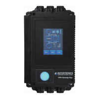
magnetic field around its periphery. As shown in Figure 1-1, this field
may rotate either clockwise or counterclockwise, depending upon
the phase sequence of the three-phase source. The speed of rotation
of this magnetic field is called “synchronous speed”.
Figure 1-1
Direction of Rotation
Magnetic
Field
CW
CCW
(End View of Motor)