Clearances
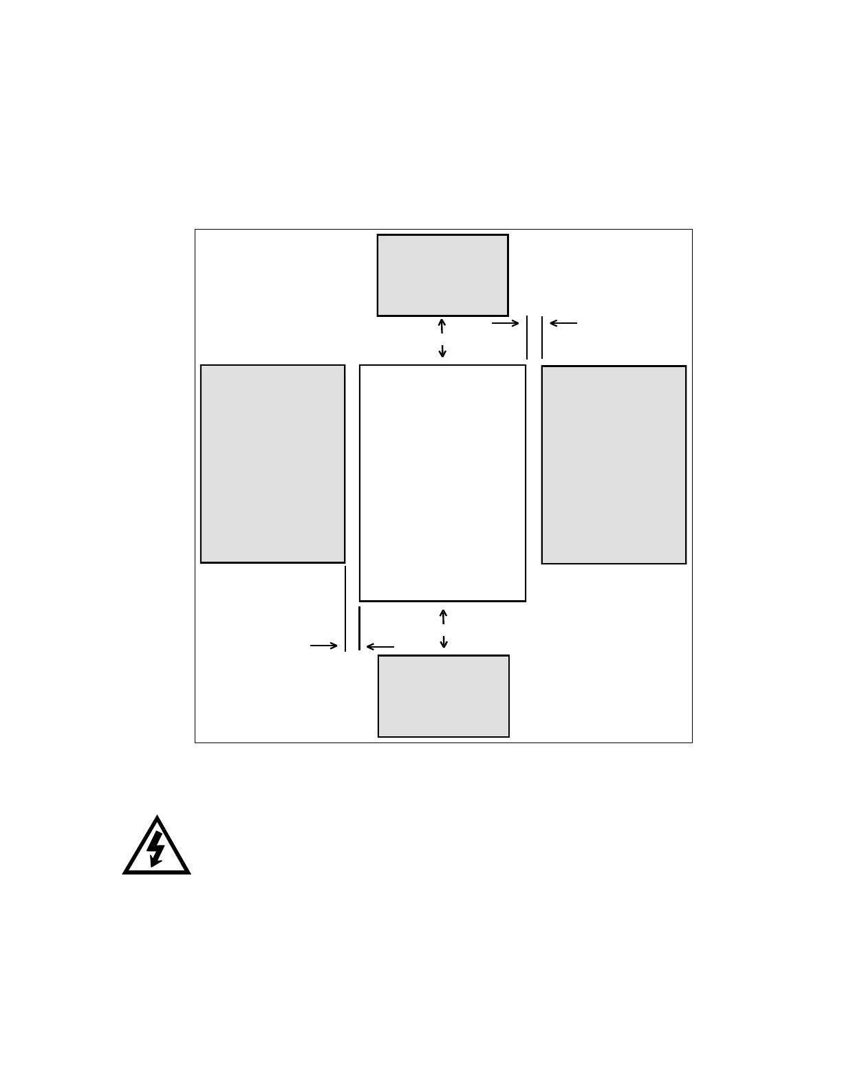
Make sure there is sufficient clearance all around the unit for cooling, wiring and maintenance purposes. To
conserve panel space, the VMX Series – BP models were designed for close vertical clearances of only 1
inch (25mm) on either side. A minimum horizontal clearance of 4” (100 mm) on the top and bottom is
necessary to maximize effective airflow and cooling. Also the unit must be installed with its heat sink ribs
oriented vertically and running parallel to the mounting surface. Keep in mind that these are minimums. Wiring
may require more clearance, particularly on the bottom.
Figure 2: VMX minimum mounting clearances
Cleaning:
WARNING!
Remove all sources of power before cleaning the unit.
In dirty or contaminated atmospheres, the unit should be cleaned on a regular basis to ensure proper
cooling. Do not use any chemicals to clean the unit. To remove surface dust use clean, dry compressed
air only, 80 to 100 psi. A three inch, high quality, dry paintbrush is helpful to loosen up the dust prior to
using compressed air on the unit. Do not use wire brushes or other conductive cleaning materials.