Motortronics
- 7 -
XLS Series Solid State Soft Starter 39 - 1250A
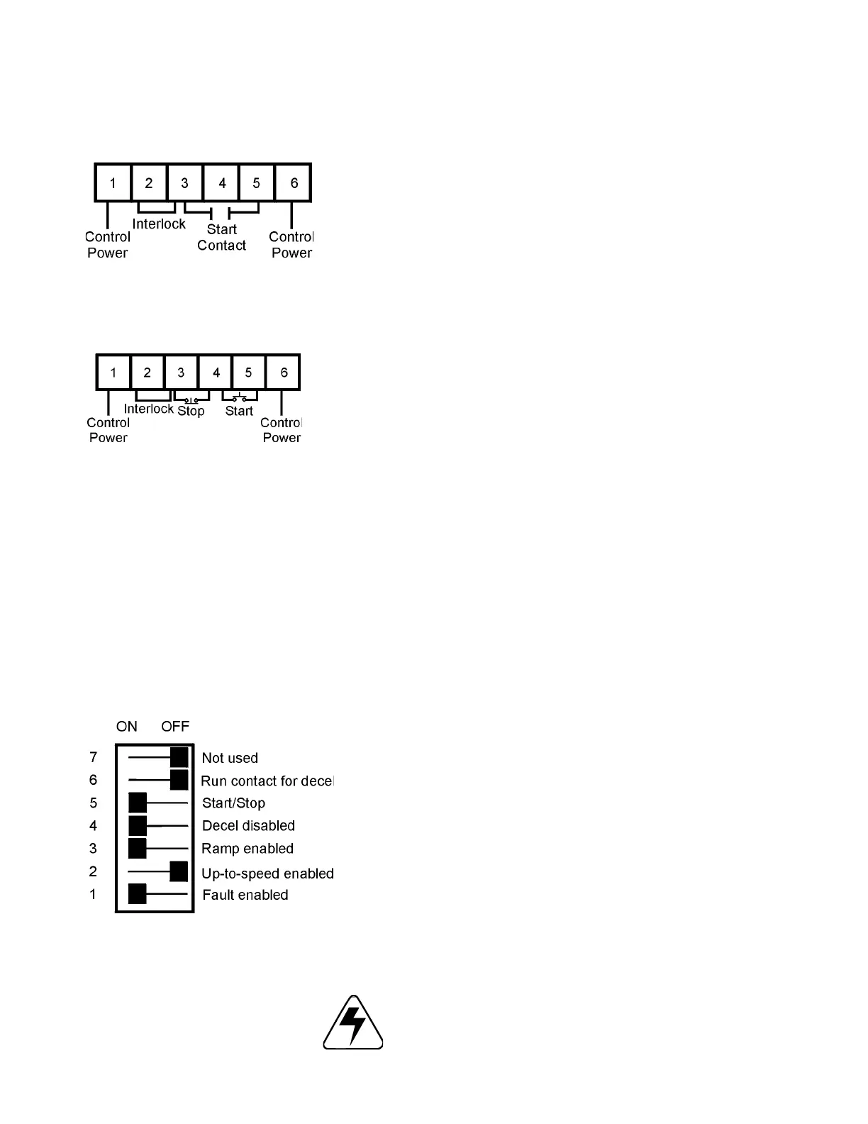
4.2.2 Two-Wire Connection
An alternate connection for unattended operation replaces start/stop
push buttons by connecting a maintained contact closure between
pins 3 and 5 on TB1. When the maintained contact is used for start/
stop it is necessary to set the overload relay to the manual reset
position. This will prevent the motor from restarting if the thermal
overload trips and then cools off (refer to Chapter 9 for 120 VAC
connections and interlocks). Note: When two-wire connection
method is used, the start circuit must be interlocked to prevent
automatic restart when either of the two protective devices
(overload or thermostat) reset. Thermostats always automatically
reset on cool down.
4.2.3 Three-Wire Connection
For standard 3-wire control connect 120VAC (or 240VAC for 415V and
380V applications) to pins 1 and 6 of TB1. Connect N.C. (normally
closed) stop button between pins 3 and 4 of TB1. Connect N.O.
(normally open) start button between pins 4 and 5 of terminal block
TB1.
4.2.4 Resetting Faults
To reset faults, remove the control power for two seconds to clear the
fault condition. The unit will also accept a remote reset command via
a N.O. dry contact at TB5 located on the main control board, or press
the reset button SW2 located near TB5. See Chapter 9 for the main
control board layout. Check the unit to ensure that the fault has been
corrected before reenergizing unit.
4.2.5 Relay Contacts
All the relay contacts are FORM C common (N.O., N.C.), except the
optical triac output. Motortronics recommends fusing all contacts with
external fuses. TB2 is the terminal block for all external contacts.
Each contact is explained in the following sections. See Chapter 9 for
main control board layout.
Two-Wire Connection
TB1
Three-Wire Connection
TB1
TB2
240 VAC
5 A
1200 VA
240 VAC
5 A
1200 VA
240 VAC
5 A
1200 VA
Optical Triac
Driver
240 VAC
50 mA
WARNING!
To make changes in the dip switch settings, the front cover of the
unit may need to be removed. Do not make adjustments with
power applied to the unit, serious injury may result. Do not use a
screwdriver or other tool to make adjustments, damage to the
unit may result.
Factory Settings
 Loading...